Flex pcb ground plane
Importance Of Ground Plane In Flex PCB Design
In the realm of flexible printed circuit boards (PCBs), the ground plane plays a pivotal role in ensuring the functionality and reliability of electronic devices. As technology advances and devices become more compact, the demand for flexible PCBs has surged, making the design considerations of these components increasingly critical. Among these considerations, the ground plane stands out as a fundamental element that significantly influences the performance of the circuit.
To begin with, the ground plane in a flex PCB serves as a reference point for all voltage levels within the circuit.
It provides a common return path for electric current, which is essential for maintaining signal integrity. Without a well-designed ground plane, the circuit is susceptible to noise and electromagnetic interference (EMI), which can degrade the performance of the device. By offering a low-impedance path, the ground plane minimizes the potential for voltage fluctuations, thereby enhancing the stability of the circuit.
Moreover, the ground plane plays a crucial role in thermal management.
As electronic components operate, they generate heat, which can adversely affect their performance and longevity. The ground plane acts as a heat sink, dissipating heat away from critical components and distributing it evenly across the board. This thermal management capability is particularly important in flexible PCBs, where the compact design and close proximity of components can lead to overheating if not properly managed.
In addition to thermal management, the ground plane also contributes to the mechanical stability of the flex PCB.
Flexible circuits are often subjected to bending and flexing, which can introduce mechanical stress. A continuous ground plane can enhance the structural integrity of the board, reducing the risk of damage during operation. This is especially important in applications where the PCB is frequently flexed, such as in wearable technology or foldable devices.
Furthermore, the ground plane is integral to the impedance control of high-speed signals.
In modern electronic devices, high-speed data transmission is common, and maintaining consistent impedance is crucial to prevent signal distortion. The ground plane helps achieve this by providing a uniform reference plane, which is essential for maintaining the characteristic impedance of transmission lines. This ensures that signals are transmitted with minimal loss and distortion, which is vital for the performance of high-speed circuits.
Transitioning to the design considerations, it is important to note that the layout of the ground plane must be carefully planned.
Designers must ensure that the ground plane is continuous and free of gaps, as discontinuities can lead to increased EMI and signal integrity issues. Additionally, the placement of vias and traces should be optimized to minimize the disruption of the ground plane. Proper grounding techniques, such as the use of ground stitching vias, can further enhance the effectiveness of the ground plane.
In conclusion, the ground plane is an indispensable component in the design of flex PCBs, influencing various aspects of circuit performance, from signal integrity and thermal management to mechanical stability and impedance control. As the demand for flexible electronics continues to grow, understanding and implementing effective ground plane design strategies will be crucial for engineers seeking to optimize the performance and reliability of their devices. By prioritizing the ground plane in the design process, engineers can ensure that their flex PCBs meet the rigorous demands of modern electronic applications.
Techniques For Optimizing Ground Plane In Flexible PCBs
In the realm of modern electronics, flexible printed circuit boards (PCBs) have emerged as a pivotal technology, offering unparalleled versatility and adaptability. One of the critical aspects of designing flexible PCBs is the optimization of the ground plane, which plays a crucial role in ensuring signal integrity, reducing electromagnetic interference (EMI), and enhancing overall performance. To achieve these objectives, several techniques can be employed, each contributing to the effective management of the ground plane in flexible PCBs.
To begin with, understanding the fundamental purpose of a ground plane is essential.
In flexible PCBs, the ground plane serves as a reference point for all signals, providing a return path for current and minimizing potential differences across the circuit. This is particularly important in high-frequency applications where signal integrity is paramount. Therefore, the first technique involves ensuring that the ground plane is continuous and unbroken. By maintaining a solid ground plane, designers can reduce impedance discontinuities, which are often the culprits behind signal degradation and EMI issues.
Moreover, the placement of vias is another critical consideration in optimizing the ground plane.
Vias, which are conductive pathways that connect different layers of a PCB, can introduce inductance and capacitance that may disrupt the ground plane’s effectiveness. To mitigate these effects, it is advisable to strategically place vias in a manner that minimizes their impact on the ground plane. For instance, using blind or buried vias can help maintain the integrity of the ground plane while still allowing for necessary interconnections between layers.
In addition to via placement, the use of stitching vias can further enhance the performance of the ground plane.
Stitching vias are small, evenly spaced vias that connect the ground plane on different layers, effectively creating a mesh-like structure. This technique helps to reduce loop areas, which are potential sources of EMI, and ensures a low-impedance path for return currents. Consequently, stitching vias contribute to improved signal integrity and reduced electromagnetic emissions.
Furthermore, the material selection for flexible PCBs can significantly influence the optimization of the ground plane.
Flexible PCBs are typically made from materials such as polyimide or polyester, which offer excellent flexibility and thermal stability. However, the dielectric properties of these materials can affect the performance of the ground plane. By selecting materials with low dielectric constants and loss tangents, designers can minimize signal attenuation and maintain a robust ground plane.
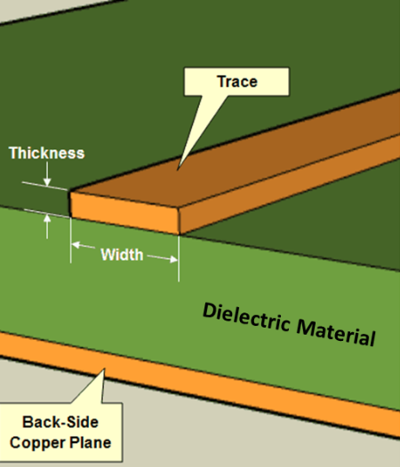
Another technique involves the careful routing of signal traces in relation to the ground plane.
It is crucial to route high-speed signal traces as close to the ground plane as possible to minimize the loop area and reduce the potential for EMI. Additionally, maintaining consistent trace widths and spacing can help ensure uniform impedance, further enhancing signal integrity.
Lastly, simulation and modeling tools play an indispensable role in optimizing the ground plane in flexible PCBs.
By utilizing advanced software tools, designers can simulate the electromagnetic behavior of the PCB and identify potential issues before fabrication. This proactive approach allows for the refinement of the ground plane design, ensuring optimal performance in the final product.
In conclusion, optimizing the ground plane in flexible PCBs is a multifaceted process that requires careful consideration of various design elements. By employing techniques such as maintaining a continuous ground plane, strategic via placement, using stitching vias, selecting appropriate materials, and leveraging simulation tools, designers can enhance the performance and reliability of flexible PCBs. These efforts ultimately contribute to the development of advanced electronic devices that meet the ever-evolving demands of modern technology.
Common Mistakes In Flex PCB Ground Plane Layout
In the realm of flexible printed circuit boards (PCBs), the ground plane plays a crucial role in ensuring the stability and performance of electronic devices. However, designing an effective ground plane in flex PCBs can be fraught with challenges, leading to common mistakes that can compromise the functionality of the entire system. Understanding these pitfalls is essential for engineers and designers aiming to optimize their designs.
One prevalent mistake in flex PCB ground plane layout is the inadequate consideration of impedance control.
Impedance mismatches can lead to signal integrity issues, which are particularly problematic in high-frequency applications. To mitigate this, it is vital to maintain a consistent ground plane across the flex PCB. This consistency helps in achieving uniform impedance, thereby reducing the risk of signal reflection and loss. Moreover, ensuring that the ground plane is continuous and free from unnecessary splits or gaps is crucial. Such discontinuities can create impedance variations, leading to electromagnetic interference (EMI) and degraded signal quality.
Another common error is the improper placement of vias, which are used to connect different layers of a PCB.
In flex PCBs, vias can disrupt the ground plane if not strategically placed. It is essential to minimize the number of vias passing through the ground plane, as each via introduces inductance and capacitance that can affect the board’s performance. When vias are necessary, they should be placed in a manner that minimizes their impact on the ground plane’s integrity. Additionally, using stitching vias around the perimeter of the ground plane can help maintain a low-inductance path, which is beneficial for EMI suppression.
Furthermore, neglecting the thermal management aspect of the ground plane can lead to significant issues.
Flex PCBs are often used in compact and portable devices where heat dissipation is a concern. The ground plane can serve as a heat spreader, but only if designed with thermal considerations in mind. Failing to account for thermal management can result in hotspots, which may lead to component failure or reduced lifespan of the device. Therefore, incorporating thermal vias and ensuring adequate copper thickness in the ground plane are strategies that can enhance heat dissipation.
In addition to these technical considerations, overlooking the mechanical properties of flex PCBs can also lead to ground plane layout mistakes.
Flex PCBs are designed to bend and flex, which means that mechanical stress is a factor that must be accounted for. Designing a ground plane that does not accommodate the mechanical movement of the board can result in cracks or delamination. To prevent such issues, it is advisable to use hatched or cross-hatched ground planes in areas that require flexibility. This approach maintains electrical performance while allowing for mechanical movement.
Lastly, failing to conduct thorough testing and simulation during the design phase is a mistake that can have far-reaching consequences.
Simulation tools can predict how the ground plane will perform under various conditions, allowing designers to identify and rectify potential issues before fabrication. By leveraging these tools, designers can ensure that their flex PCB ground plane layout is optimized for both electrical performance and mechanical reliability.
In conclusion, while designing a flex PCB ground plane presents unique challenges, understanding and avoiding common mistakes can lead to more robust and reliable electronic devices. By focusing on impedance control, via placement, thermal management, mechanical properties, and thorough testing, designers can create effective ground plane layouts that enhance the overall performance of flex PCBs.
Benefits Of Using Ground Plane In Flex PCB Applications
In the realm of flexible printed circuit boards (flex PCBs), the incorporation of a ground plane is a critical design consideration that offers numerous benefits, enhancing both the performance and reliability of electronic devices. As electronic devices continue to shrink in size while increasing in complexity, the demand for efficient and reliable circuit designs has never been greater. Flex PCBs, known for their ability to bend and conform to various shapes, are increasingly utilized in applications ranging from consumer electronics to medical devices. Within these applications, the ground plane plays a pivotal role in optimizing the functionality of the circuit.
One of the primary advantages of using a ground plane in flex PCB applications is the significant reduction in electromagnetic interference (EMI)
. EMI can adversely affect the performance of electronic devices by causing signal distortion and data loss. By providing a continuous conductive surface, the ground plane acts as a shield that absorbs and redirects electromagnetic waves, thereby minimizing interference. This is particularly beneficial in high-frequency applications where signal integrity is paramount. Moreover, the ground plane helps in maintaining a consistent impedance across the circuit, which is crucial for high-speed signal transmission. This consistency ensures that signals are transmitted with minimal reflection and loss, thereby enhancing the overall performance of the device.
In addition to mitigating EMI, the ground plane also plays a crucial role in improving thermal management within flex PCBs.
As electronic components become more powerful, they generate more heat, which can lead to performance degradation or even failure if not properly managed. The ground plane serves as a heat sink, dissipating heat away from critical components and distributing it evenly across the board. This not only helps in maintaining optimal operating temperatures but also extends the lifespan of the components by preventing overheating. Furthermore, the use of a ground plane can reduce the need for additional thermal management solutions, such as heat sinks or fans, thereby saving space and reducing the overall weight of the device.
Another significant benefit of incorporating a ground plane in flex PCB designs is the enhancement of mechanical stability.
Flex PCBs are often subjected to bending, twisting, and other mechanical stresses during installation and operation. The ground plane adds structural integrity to the board, reducing the risk of damage due to mechanical stress. This is particularly important in applications where the PCB is frequently flexed or bent, such as in wearable devices or foldable electronics. By providing additional support, the ground plane helps ensure the long-term reliability and durability of the circuit.
Moreover, the ground plane facilitates easier routing of signal traces by providing a common reference point for all signals.
This simplifies the design process and can lead to more compact and efficient layouts. The presence of a ground plane also reduces the number of vias required for signal routing, which can further enhance the reliability of the circuit by minimizing potential points of failure.
In conclusion, the integration of a ground plane in flex PCB applications offers a multitude of benefits that are essential for modern electronic devices. From reducing electromagnetic interference and improving thermal management to enhancing mechanical stability and simplifying design, the ground plane is a vital component that contributes to the overall performance and reliability of flex PCBs. As technology continues to advance, the importance of incorporating a ground plane in flex PCB designs will only continue to grow, ensuring that electronic devices meet the ever-increasing demands of today’s consumers.