Flying Probe Testing in PCB Manufacturing: A Comprehensive Guide
Introduction to Flying Probe Testing
In the rapidly evolving world of printed circuit board (PCB) manufacturing, quality assurance and testing have become critical components of the production process. Among the various testing methodologies available, Flying Probe Testing (FPT) has emerged as a versatile, cost-effective solution for verifying the electrical integrity of PCBs, especially in low-to-medium volume production and prototyping environments.
Flying Probe Testing represents a significant advancement over traditional testing methods, offering manufacturers greater flexibility, faster setup times, and the ability to handle complex board designs without requiring custom fixtures. This non-intrusive testing approach uses movable probes to access test points on a PCB, performing continuity, isolation, and component verification tests with high precision.
As electronic devices continue to become more complex while product lifecycles shorten, the importance of reliable, adaptable testing solutions like FPT continues to grow. This article will explore the technology behind flying probe testing, its advantages and limitations, implementation considerations, and its role in modern PCB manufacturing.
The Technology Behind Flying Probe Testing
Basic Working Principle
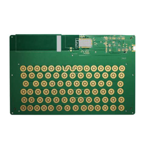
Flying Probe Testing systems consist of two or more movable probes mounted on robotic arms that can move independently in three dimensions (X, Y, and Z axes). These probes serve as the interface between the test system and the PCB, making electrical contact with test points to perform various measurements.
The testing process begins with the PCB being securely mounted on the test fixture. The system then uses pre-programmed instructions to position the probes precisely on designated test points. The probes descend (Z-axis movement) to make contact with the board, apply test signals, measure responses, and then retract to move to the next set of test points.
Key Components of an FPT System
- Probe Mechanisms: Modern flying probe testers typically feature 4-8 probes, with high-end systems sometimes offering even more. These probes are designed for precise positioning and reliable contact. They often include:
- Spring-loaded tips to ensure proper contact pressure
- Replaceable tips for different pad types (sharp for small pads, flat for larger areas)
- Built-in sensing to detect proper contact
- Motion Control System: The robotic positioning system uses high-precision servo motors or linear motors with optical encoders to achieve positioning accuracy typically in the range of ±10-25 microns.
- Measurement Hardware: This includes:
- Precision analog instrumentation for resistance measurements
- High-frequency capability for testing impedance and high-speed signals
- Advanced digital testing capabilities for programmable devices
- Vision Systems: Many modern FPT systems incorporate cameras for:
- Board alignment verification
- Component presence detection
- Probe placement verification
- Optical inspection functions
- Software Suite: Comprehensive software handles:
- Test program generation (often from CAD data)
- Test sequencing and optimization
- Data collection and analysis
- Reporting and diagnostics
Test Capabilities
Flying probe testers can perform a wide range of tests, including:
- Continuity Testing: Verifies that connections exist where they should according to the netlist.
- Isolation Testing: Ensures no unwanted connections exist between separate nets.
- Component Verification: Checks passive component values (resistors, capacitors, inductors).
- Diode and Transistor Testing: Verifies proper orientation and basic functionality.
- Advanced Measurements: Some systems can measure:
- Impedance of transmission lines
- High-frequency characteristics
- Programming and testing of flash memory and other programmable devices
Advantages of Flying Probe Testing
No Fixture Requirements
One of the most significant advantages of FPT is the elimination of custom test fixtures required by traditional bed-of-nails testing. This provides several benefits:
- Lower Initial Costs: No need to design and manufacture expensive test fixtures.
- Faster Time-to-Market: Testing can begin as soon as the first prototype is available.
- Design Flexibility: Changes to the PCB design don’t require fixture modifications.
Flexibility and Adaptability
FPT systems excel in environments where:
- Product Designs Change Frequently: The test program can be quickly updated to accommodate design changes.
- Multiple Variants Exist: A single tester can handle different board versions without hardware changes.
- High-Mix Production: Quick changeover between different board types is possible.
Cost-Effectiveness for Low/Medium Volumes
For production runs where the cost of a bed-of-nails fixture cannot be justified, FPT offers:
- No Per-Board Fixture Cost: The economics become favorable compared to fixtures at certain volume breakpoints.
- Better ROI for Prototyping: Ideal for new product introduction phases.
- Reduced Storage Needs: No physical fixtures to store and maintain.
Advanced Testing Capabilities
Modern FPT systems offer sophisticated testing features:
- High-Density Board Testing: Capable of testing fine-pitch components and high-density interconnects.
- Double-Sided Testing: Probes can access both sides of the board simultaneously.
- RF Testing: Some systems include high-frequency measurement capabilities.
- Boundary Scan Support: Integration with JTAG/boundary scan testing.
Limitations and Challenges
While FPT offers numerous advantages, there are some limitations to consider:
Throughput Considerations
- Slower Than Fixture-Based Testing: Moving probes take more time than simultaneous contact with a bed-of-nails.
- Test Time Increases with Complexity: More test points mean longer test times.
- Not Ideal for High-Volume Production: For very large volumes, the per-unit test time may become prohibitive.
Access Limitations
- Physical Probe Access Required: Some areas may be inaccessible due to component height or board features.
- Limited Number of Simultaneous Measurements: Typically only a few probes are active at any given time.
- Challenges with Certain Components: Some components (like BGAs) may be difficult to probe directly.
Measurement Limitations
- Limited Power Testing: Most systems can’t apply significant power to the board.
- Frequency Limitations: While improving, very high-frequency testing may require supplemental methods.
- Limited Functional Testing: Comprehensive functional testing usually requires additional equipment.
Implementing Flying Probe Testing
Test Program Development
Creating an effective FPT program involves several steps:
- Data Import: Typically starting with CAD data (Gerber, ODB++, IPC-2581) or netlist files.
- Test Point Identification: Automatic or manual selection of optimal test points.
- Test Strategy Definition: Determining which tests to perform and in what sequence.
- Path Optimization: Software algorithms optimize probe movement to minimize test time.
- Fixture Definition: If any custom fixturing is needed for board support or alignment.
System Selection Criteria
When choosing an FPT system, consider:
- Number of Probes: More probes can reduce test time but increase system cost.
- Positioning Accuracy: Should match your PCB feature sizes.
- Measurement Capabilities: Ensure it meets your testing requirements.
- Software Features: Look for intuitive programming and good diagnostic tools.
- Throughput Requirements: Match the system’s capacity to your production needs.
- Expandability: Options for adding capabilities like high-frequency testing.
Integration into Production Flow
Effective implementation requires:
- Process Planning: Determining where FPT fits in your overall test strategy.
- Operator Training: Proper training maximizes system utilization.
- Maintenance Planning: Regular calibration and probe maintenance.
- Quality Metrics: Establishing benchmarks and monitoring test effectiveness.
Advanced Applications and Future Trends
Combined Optical and Electrical Testing
Some modern systems combine FPT with:
- Automated Optical Inspection (AOI): Visual checks alongside electrical tests.
- 3D Measurement: Component height and coplanarity verification.
- X-ray Inspection: For hidden connections like BGA joints.
High-Frequency Testing
Advancements in probe technology now allow:
- Impedance Testing: For high-speed digital circuits.
- RF Characterization: Up to several GHz in some systems.
- Signal Integrity Verification: Checking transmission line quality.
Smart Factory Integration
Future trends include:
- Industry 4.0 Connectivity: Integration with factory IoT systems.
- AI-Based Test Optimization: Machine learning for test sequence optimization.
- Predictive Maintenance: Using operational data to anticipate maintenance needs.
- Digital Twin Integration: Linking test results with virtual board models.
Conclusion
Flying Probe Testing has established itself as an indispensable tool in modern PCB manufacturing, particularly for prototyping, low-to-medium volume production, and high-mix environments. By eliminating the need for custom test fixtures, FPT provides manufacturers with unprecedented flexibility and significantly reduces the time and cost associated with bringing new designs to market.
While traditional bed-of-nails testing remains more appropriate for very high-volume production of stable designs, the capabilities of FPT systems continue to expand, narrowing the gap in both throughput and test coverage. Advances in probe technology, measurement capabilities, and system intelligence ensure that FPT will remain at the forefront of PCB testing solutions.
As electronic products continue their trend toward greater complexity, miniaturization, and shorter lifecycles, the importance of adaptable testing solutions like Flying Probe Testing will only increase. Manufacturers who effectively implement FPT as part of a comprehensive test strategy will be well-positioned to meet the challenges of tomorrow’s electronics marketplace while maintaining high quality standards and rapid time-to-market.


