Grounding Techniques for PCB Design Considering EMC
In PCB design, grounding is a crucial measure for suppressing noise and preventing interference. Different grounding methods are used depending on the circuit. Only proper grounding can reduce or avoid mutual interference between circuits. There are two main grounding methods in daily life: single-point grounding and multi-point grounding. This article will focus on how to properly ground while considering EMC, and hopefully provide some valuable insights for electronics designers.
1.Eliminating Ground Interference
In some cases, interference caused by ground line impedance is unavoidable, especially for electronic devices. Ideally, ground line impedance is zero. It not only serves as a reference point for signal levels in the circuit, but also should not produce a voltage drop when current flows through it. However, such an ideal ground line does not exist in specific electronic devices. Ground lines have both resistance and reactance, and when current flows through them, a voltage drop is inevitable. Furthermore, ground lines can form loops with other lines (signal lines, power lines). When an alternating magnetic field intersects with this loop, an electromotive force is induced in the ground line. Whether the current flowing through the ground line is in the ground, the ground line will be affected by the current flowing through it. Whether it’s voltage drops on the line or inductive potentials caused by ground loops, these can cause mutual interference between circuit units sharing a common ground line. Suppressing ground interference has become a key issue in electromagnetic compatibility design. Based on the mechanism of ground interference formation, measures to reduce ground interference can be summarized as follows: separating analog and digital grounds, reducing ground impedance and source and feeder impedance, selecting an appropriate grounding method, and blocking ground loops. Interference voltage in the ground line is related not only to the current flowing through it but also to the ground impedance. Ground impedance consists of resistance and inductance.
ZG = RG + jwL
(1) If you want to reduce ZG, you have to reduce RG and L. However, when AC flows through the conductor cross section, it is not evenly distributed on the conductor like DC. Due to the skin effect, the current is concentrated on the surface, making the effective current-carrying area of the conductor smaller than or even much smaller than the actual cross-sectional area of the conductor. Therefore, the impedance of the same conductor in DC, low frequency and high frequency conditions is different; and the inductance of the conductor is also related to the conductor radius, length and signal frequency. When designing, the conductor cross-sectional size should be selected according to the conductor impedance at different frequencies, and the ground wire should be thickened and shortened as much as possible. 2. General selection principles of grounding method For a given device or system, at the highest frequency of interest (corresponding to the wavelength) λ, when the length of the transmission line L>λ, it is considered a high-frequency circuit, otherwise it is considered a low-frequency circuit. According to the rule of thumb, for circuits below 1MHZ, single-point grounding is better; for circuits above 10MHZ, multi-point grounding is better. For frequencies between the two, as long as the length of the longest transmission line L is less than /20λ, single-point grounding can be used to avoid common impedance coupling. The general selection principles for grounding are as follows: (1) For low-frequency circuits (<1MHZ), it is recommended to use single-point grounding; (2) For high-frequency circuits (>10MHZ), it is recommended to use multi-point grounding; (3) For mixed high- and low-frequency circuits, use mixed grounding. III. Grounding methods 1. Single-point grounding Single-point grounding means that there is only one physical point in the entire system that is defined as the ground reference point, and all other points that need to be grounded are connected to this point. Single-point grounding is suitable for circuits with lower frequencies (below 1MHZ). If the operating frequency of the system is very high, so that the operating wavelength is comparable to the length of the system ground lead, the single-point grounding method will have problems. When the length of the ground line is close to 1/4 wavelength, it is like a transmission line with a short circuit at the end. The current and voltage of the ground line are distributed in a standing wave pattern, and the ground line becomes a radiating antenna and cannot play the role of “ground”. In order to reduce the grounding impedance and avoid radiation, the length of the ground line should be less than 1/20 wavelength. In the processing of power supply circuits, single-point grounding can generally be considered. Single-point grounding is generally not recommended for PCBs that utilize extensive digital circuits due to their high harmonic content.
2.Multi-point Grounding
Multi-point grounding connects each ground point in the device directly to the nearest ground plane, minimizing the length of the ground lead.
Multi-point grounding simplifies the circuit structure and significantly reduces high-frequency standing waves that may occur on the ground line. It is suitable for applications with higher operating frequencies (>10 MHz). However, multi-point grounding can lead to the formation of numerous ground loops within the device, reducing its resistance to external electromagnetic fields. When using multi-point grounding, be mindful of ground loops, especially when networking different modules and devices. Electromagnetic interference caused by ground loops:
An ideal ground line should be a physical entity with zero potential and zero impedance. However, a real ground line has both resistance and reactance components, generating a voltage drop when current flows through it. The ground wire forms a loop with other wires (signal and power lines, etc.). When a time-varying electromagnetic field couples into this loop, an induced electromotive force is generated in the ground loop. This ground loop then couples to the load, posing a potential EMI threat.
3.Floating Ground
Floating ground refers to a grounding method in which the equipment ground system is electrically isolated from the earth.
Due to its inherent weaknesses, floating grounding is not suitable for large systems and is rarely used.
4 Conclusion
Properly choose between single-point and multi-point grounding. When the frequency is below 1MHz, single-point grounding should be used; when the frequency is above 10MHz, multi-point grounding should be used nearby. When the operating frequency is between 1-10MHz, if single-point grounding is used, the ground wire length should not exceed 1/20 of the wavelength; otherwise, multi-point grounding should be used. Use symmetrical, balanced circuit structures and twisted-pair shielded cables for transmission lines so that the ground noise and other interference received by both lines are equal, canceling each other out at the input. The shield layer of the shielded conductor should be grounded at one end, either to the amplifier common terminal or the signal source common terminal. Circuit boards contain both high-speed logic circuits and linear circuits; keep them as separate as possible, and avoid mixing their ground wires. Connect each to the power supply ground wire. Increase the cross-sectional area of the linear circuit ground wire to ensure it can carry three times the current of the printed circuit board. If possible, the ground wire diameter should be greater than 3mm.
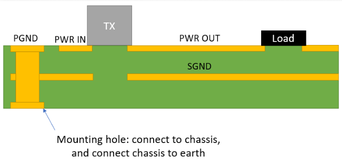
There are large currents passing through the load ground wire and the AC ground wire. These large current ground wires should be separated from the signal ground. At the same time, the large current ground wire should be thicker. Usually, a bus or thick wire should be used. Various types of ground wires should be wired separately. Then, the same type of ground wires should be short-circuited and then connected to a common grounding point. If some of them are not allowed to be directly connected, a 1-10uf capacitor can be added between the two. In order to achieve better results, the copper mesh is often buried deep in the ground, and then connected to the common grounding point with a copper busbar.