High frequency rf pcb
Design Techniques for High Frequency RF PCBs
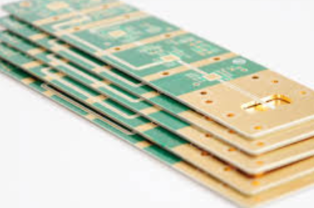
Designing high frequency RF PCBs requires a meticulous approach to ensure optimal performance and reliability. The first step in this process involves selecting the appropriate materials. High frequency applications demand substrates with low dielectric constants and minimal loss tangents to reduce signal attenuation and maintain signal integrity. Materials such as Rogers, Taconic, and PTFE-based laminates are often preferred due to their superior electrical properties compared to standard FR-4 substrates.
Once the material is chosen, the next critical aspect is the layout design.
The layout must minimize signal loss and interference, which can be achieved through careful trace routing. For high frequency signals, the traces should be as short and direct as possible to reduce inductance and capacitance. Additionally, maintaining consistent trace width and spacing is crucial to avoid impedance mismatches, which can lead to signal reflections and degradation. Microstrip and stripline configurations are commonly used in high frequency designs to control impedance and ensure signal integrity.
Ground planes play a vital role in high frequency RF PCB design.
A continuous ground plane helps to reduce electromagnetic interference (EMI) and provides a return path for signals, which is essential for maintaining signal integrity. It is advisable to use a multilayer PCB with dedicated ground and power planes to further enhance performance. Stitching vias should be employed to connect the ground planes across different layers, thereby reducing ground loop areas and minimizing potential EMI issues.
Component placement is another critical factor in high frequency RF PCB design.
Placing components too close to each other can lead to crosstalk and signal coupling, which can degrade performance. Therefore, it is essential to strategically place components to minimize these effects. High frequency components, such as oscillators and amplifiers, should be placed as close to their associated circuitry as possible to reduce trace lengths and potential signal loss. Additionally, sensitive components should be shielded from high power components to prevent interference.
The use of proper decoupling and bypass capacitors is also crucial in high frequency designs.
These capacitors help to filter out noise and provide a stable power supply to the components. It is important to place these capacitors as close to the power pins of the components as possible to maximize their effectiveness. Furthermore, selecting capacitors with appropriate values and low equivalent series resistance (ESR) is essential for high frequency applications.
Thermal management cannot be overlooked in high frequency RF PCB design.
High frequency components often generate significant heat, which can affect performance and reliability. Therefore, it is important to incorporate thermal vias, heat sinks, and adequate ventilation into the design to dissipate heat effectively. Using materials with good thermal conductivity can also help in managing heat dissipation.
Finally, simulation and testing are indispensable steps in the design process.
Simulation tools can help predict the behavior of the PCB under various conditions and identify potential issues before fabrication. Once the PCB is fabricated, thorough testing should be conducted to ensure it meets the desired performance specifications. This includes testing for signal integrity, EMI, and thermal performance.
In conclusion, designing high frequency RF PCBs requires careful consideration of material selection, layout design, ground planes, component placement, decoupling, thermal management, and thorough testing. By adhering to these design techniques, engineers can create high frequency RF PCBs that deliver reliable and optimal performance.
Material Selection for High Frequency RF PCBs
When designing high frequency RF PCBs, the selection of materials is a critical factor that significantly influences the performance, reliability, and overall functionality of the final product. The unique demands of high frequency applications necessitate careful consideration of various material properties to ensure optimal signal integrity and minimal loss. Consequently, understanding the key attributes of potential materials is essential for engineers and designers working in this specialized field.
One of the primary considerations in material selection for high frequency RF PCBs is the dielectric constant (Dk).
The dielectric constant affects the speed at which signals propagate through the PCB material. For high frequency applications, materials with a low and stable dielectric constant are preferred, as they help maintain signal integrity and reduce signal loss. Common materials used in these applications include PTFE (Polytetrafluoroethylene), also known as Teflon, and ceramic-filled laminates. These materials offer low dielectric constants and exhibit minimal variation with frequency, making them suitable for high frequency RF circuits.
In addition to the dielectric constant, the dissipation factor (Df) is another crucial parameter.
The dissipation factor measures the dielectric losses within the material, which directly impacts the efficiency of signal transmission. Materials with a low dissipation factor are desirable for high frequency RF PCBs because they minimize energy loss and heat generation, thereby enhancing the overall performance of the circuit. PTFE-based materials, for instance, are known for their low dissipation factors, making them a popular choice in high frequency applications.
Thermal management is another important aspect to consider when selecting materials for high frequency RF PCBs.
High frequency circuits often generate significant amounts of heat, which can adversely affect the performance and longevity of the PCB. Therefore, materials with good thermal conductivity are essential to dissipate heat effectively and maintain stable operating temperatures. Ceramic-filled laminates and certain PTFE composites offer excellent thermal conductivity, making them suitable for high frequency RF applications where thermal management is a concern.
Moreover, the mechanical properties of the material play a vital role in the overall reliability and durability of the PCB.
High frequency RF PCBs are often subjected to various environmental stresses, including temperature fluctuations, mechanical vibrations, and humidity. Therefore, materials with robust mechanical properties, such as high tensile strength and dimensional stability, are preferred to ensure the longevity and reliability of the PCB. PTFE-based materials, while offering excellent electrical properties, can be mechanically challenging to work with due to their softness and flexibility. In such cases, reinforced PTFE composites or ceramic-filled laminates can provide a good balance between electrical performance and mechanical robustness.
Furthermore, the ease of fabrication and processing is a practical consideration in material selection.
High frequency RF PCBs often require precise manufacturing techniques to achieve the desired performance characteristics. Materials that are compatible with standard PCB fabrication processes, such as drilling, plating, and etching, are advantageous as they simplify the manufacturing process and reduce production costs. PTFE-based materials, while offering superior electrical properties, may require specialized processing techniques, which can increase manufacturing complexity and cost. Therefore, selecting materials that strike a balance between performance and manufacturability is crucial for efficient production.
In conclusion, the selection of materials for high frequency RF PCBs is a multifaceted decision that involves evaluating various electrical, thermal, mechanical, and practical considerations. By carefully assessing the dielectric constant, dissipation factor, thermal conductivity, mechanical properties, and ease of fabrication, engineers and designers can choose materials that meet the stringent requirements of high frequency applications. This meticulous approach ensures the development of high-performance, reliable, and cost-effective RF PCBs that can effectively meet the demands of modern communication and electronic systems.

Challenges in Manufacturing High Frequency RF PCBs
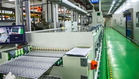
Manufacturing high frequency RF PCBs presents a unique set of challenges that require specialized knowledge and precision. One of the primary difficulties lies in the selection of materials. Unlike standard PCBs, high frequency RF PCBs necessitate substrates with low dielectric constants and minimal loss tangents to ensure signal integrity. Materials such as PTFE (Polytetrafluoroethylene) and ceramic-filled laminates are often preferred, but they come with their own set of complications. These materials are not only more expensive but also more difficult to handle during the manufacturing process, requiring specialized equipment and techniques.
In addition to material selection, the design of high frequency RF PCBs demands meticulous attention to detail.
The layout must be optimized to minimize signal loss and interference, which involves careful consideration of trace width, spacing, and the overall geometry of the circuit. Impedance control is critical, as any deviation can lead to signal reflection and degradation. This necessitates precise calculations and often iterative simulations to ensure that the design meets the stringent requirements of high frequency applications.
Thermal management is another significant challenge in the manufacturing of high frequency RF PCBs
. High frequency signals generate more heat, which can affect the performance and reliability of the PCB. Effective thermal management strategies, such as the use of thermal vias, heat sinks, and appropriate substrate materials, are essential to dissipate heat efficiently. However, integrating these solutions without compromising the electrical performance of the PCB adds another layer of complexity to the design and manufacturing process.
Moreover, the manufacturing tolerances for high frequency RF PCBs are much tighter compared to standard PCBs.
Even minor deviations in the etching process can lead to significant performance issues. This requires advanced manufacturing techniques and rigorous quality control measures to ensure that each PCB meets the required specifications. Techniques such as laser direct imaging (LDI) and automated optical inspection (AOI) are often employed to achieve the necessary precision and consistency.
The assembly process also poses challenges, particularly in the placement and soldering of components.
High frequency RF components are often smaller and more sensitive to placement accuracy. Any misalignment can lead to performance degradation or even failure of the PCB. Therefore, advanced pick-and-place machines and reflow soldering techniques are essential to ensure accurate and reliable assembly.
Furthermore, testing and validation of high frequency RF PCBs are more complex and time-consuming.
Standard testing methods may not be sufficient to identify issues that can affect high frequency performance. Specialized testing equipment, such as network analyzers and spectrum analyzers, are required to thoroughly evaluate the PCB’s performance. This adds to the overall cost and time required for manufacturing.
In conclusion, the manufacturing of high frequency RF PCBs is fraught with challenges that span material selection, design, thermal management, manufacturing tolerances, assembly, and testing. Each of these aspects requires specialized knowledge, advanced techniques, and rigorous quality control measures to ensure the final product meets the stringent requirements of high frequency applications. As technology continues to advance, the demand for high frequency RF PCBs is expected to grow, making it imperative for manufacturers to continually innovate and refine their processes to overcome these challenges.
Testing and Validation of High Frequency RF PCBs
Testing and validation of high frequency RF PCBs are critical steps in ensuring the reliability and performance of these sophisticated electronic components. High frequency RF PCBs, which operate at frequencies typically above 1 GHz, are integral to a wide range of applications, including telecommunications, radar systems, and advanced medical devices. Given the complexity and precision required in these applications, rigorous testing and validation processes are essential.
To begin with, the testing of high frequency RF PCBs involves a series of electrical and mechanical assessments.
Electrical testing is paramount, as it verifies the functionality and performance of the PCB under operational conditions. This includes measuring parameters such as impedance, signal integrity, and power handling capabilities. Impedance control is particularly crucial in high frequency applications, as any deviation can lead to signal reflection and loss, thereby degrading the overall performance of the PCB. Advanced tools like vector network analyzers (VNAs) are often employed to measure these parameters with high accuracy.
In addition to electrical testing, mechanical testing is also vital.
This involves assessing the physical robustness of the PCB, including its ability to withstand thermal cycling, vibration, and mechanical stress. High frequency RF PCBs are often used in environments where they are subjected to extreme conditions, and any mechanical failure can lead to catastrophic consequences. Therefore, tests such as thermal shock, vibration testing, and mechanical bend tests are conducted to ensure the PCB can endure these conditions without compromising its performance.
Following the initial testing phase, validation processes are implemented to confirm that the PCB meets all specified requirements and standards.
Validation is a comprehensive process that includes both design validation and process validation. Design validation ensures that the PCB design meets the intended performance criteria and complies with industry standards. This often involves simulation and modeling techniques to predict the behavior of the PCB under various conditions. Tools such as electromagnetic simulation software are used to model the high frequency behavior of the PCB and identify any potential issues before physical prototypes are built.
Process validation, on the other hand, focuses on the manufacturing process.
It ensures that the production methods used to fabricate the PCB are capable of consistently producing units that meet the required specifications. This involves a series of controlled experiments and statistical analyses to verify that the manufacturing process is stable and capable. Process validation is particularly important for high frequency RF PCBs, as even minor variations in the manufacturing process can lead to significant performance deviations.
Moreover, environmental testing is an integral part of the validation process.
High frequency RF PCBs must be able to operate reliably in a variety of environmental conditions, including extreme temperatures, humidity, and electromagnetic interference. Environmental tests such as temperature cycling, humidity testing, and electromagnetic compatibility (EMC) testing are conducted to ensure the PCB can perform reliably in its intended operating environment.
In conclusion, the testing and validation of high frequency RF PCBs are multifaceted processes that encompass electrical, mechanical, and environmental assessments. These processes are essential to ensure that the PCBs meet the stringent performance and reliability requirements of high frequency applications. By employing advanced testing tools and rigorous validation techniques, manufacturers can ensure that their high frequency RF PCBs deliver optimal performance and reliability in even the most demanding applications.

