How to Make Rigid Flex PCB
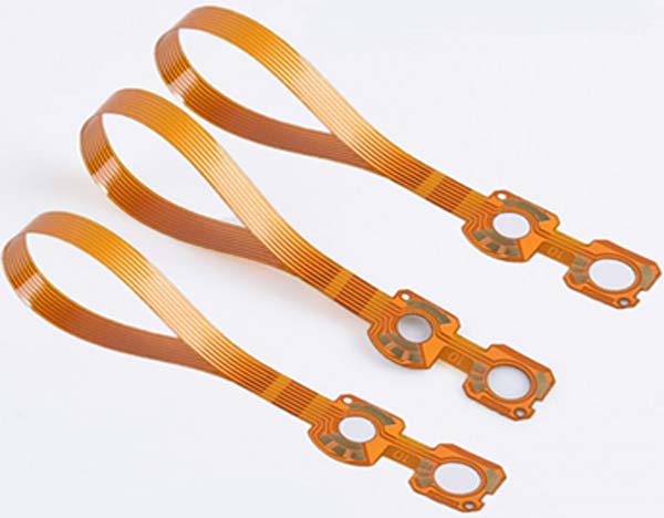
Rigid-flex PCBs, also known as flexible printed circuit boards, offer a unique combination of flexibility and rigidity that makes them ideal for a wide range of applications. These boards have the ability to bend and twist without compromising their functionality, making them suitable for use in devices that require both flexibility and durability. In this article, we will explore the process of making rigid-flex PCBs.
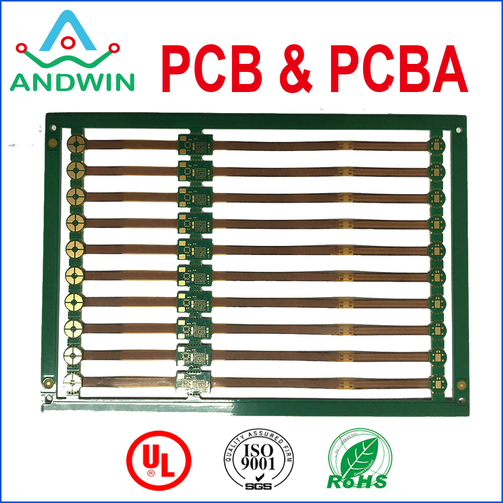
1. Designing the PCB:
The first step in making a rigid-flex PCB is to design the circuit layout. This involves determining the size and shape of the board, as well as placing the components and traces in the desired configuration. Special attention must be paid to the areas where the board will flex, ensuring that the traces and components are properly positioned to avoid stress and strain.
2. Material Selection:
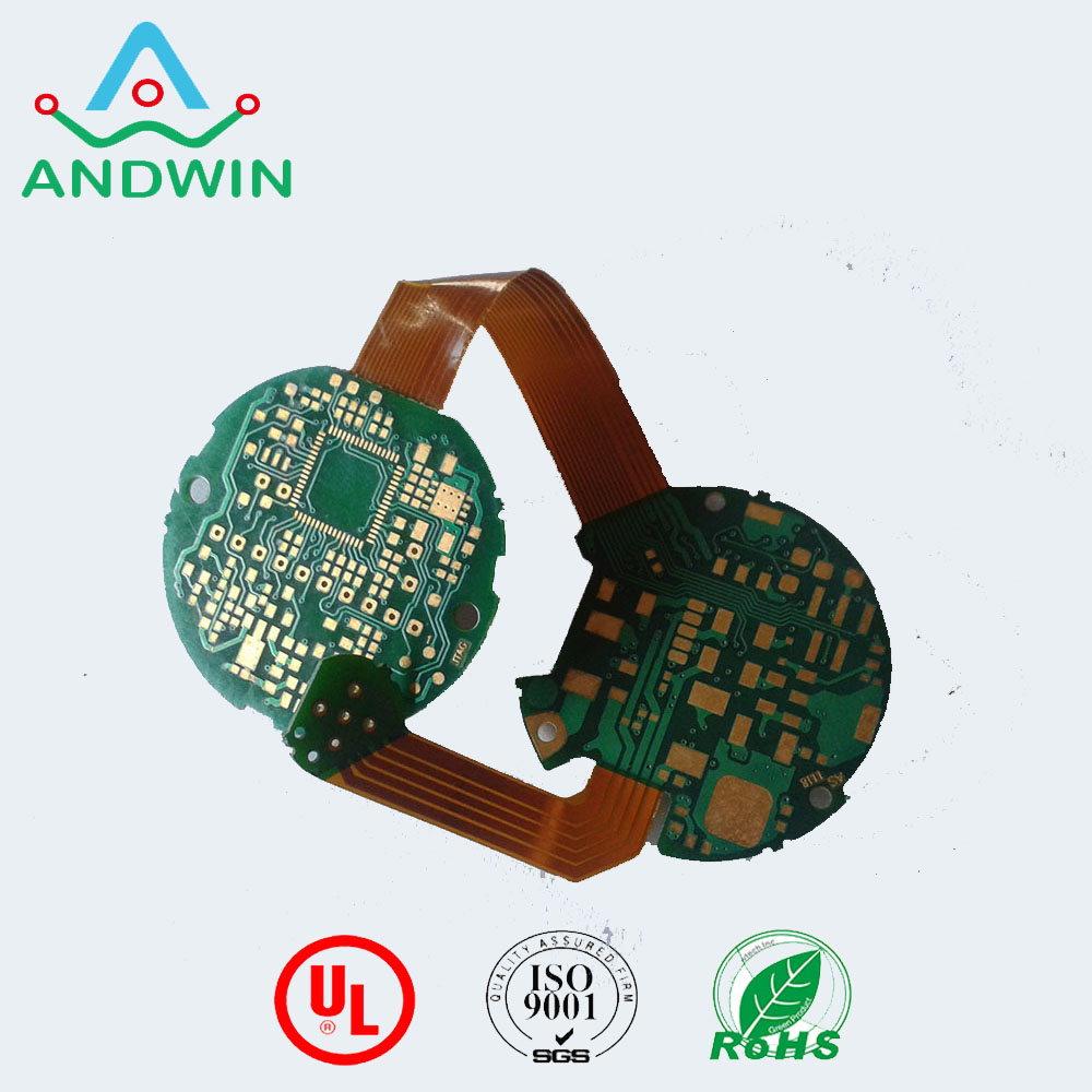
Choosing the right materials is crucial for the success of a rigid-flex PCB. The flexible portion of the board is typically made of polyimide, a durable and flexible material that can withstand repeated bending. The rigid sections are usually made of FR4, a rigid and flame-resistant material commonly used in traditional PCBs.
3. Manufacturing Process:
The manufacturing process for rigid-flex PCBs involves several steps. First, the flexible material is coated with a layer of adhesive and then laminated with the rigid material. This creates a single, unified board with both flexible and rigid sections. Next, the circuit pattern is etched onto the board using a chemical process. This is followed by the drilling of holes for component placement and the application of a protective solder mask.
4. Component Placement:
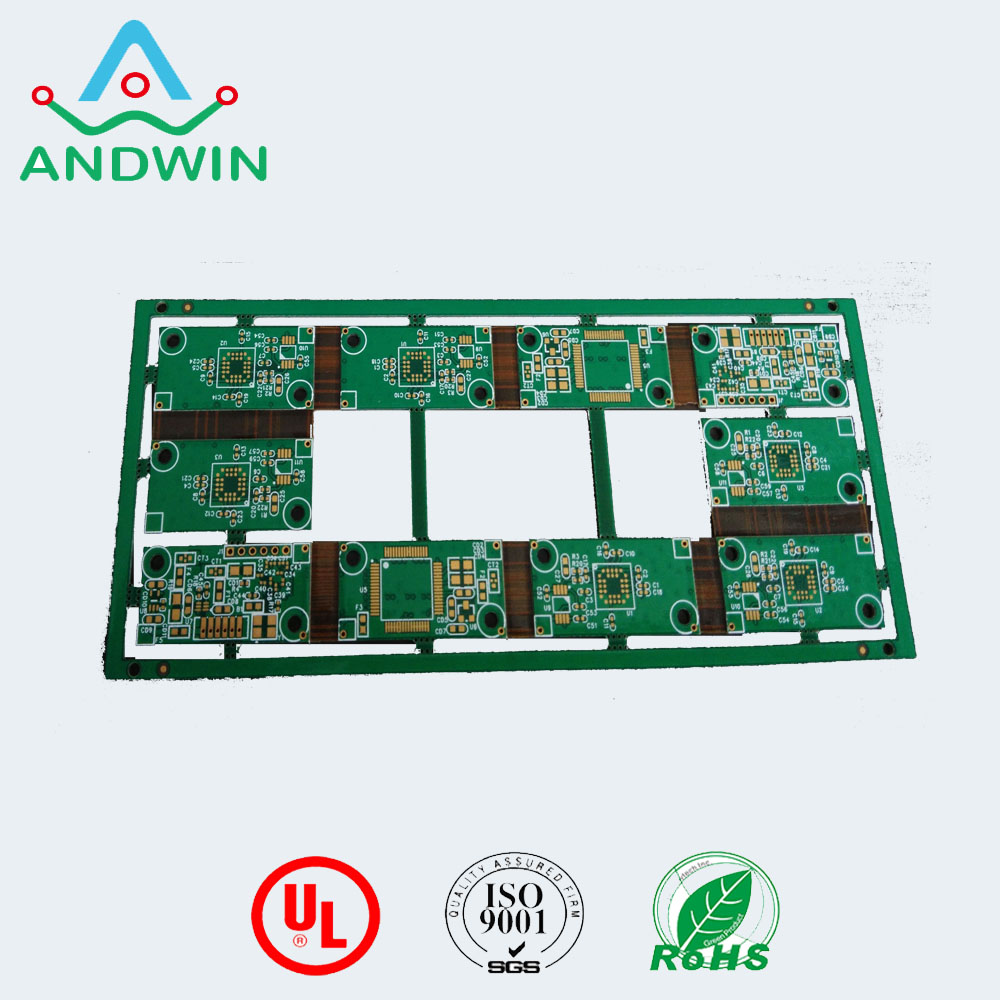
Once the board is manufactured, the next step is to place the components. This is done using automated pick-and-place machines that precisely position the components onto the board. Special care must be taken to ensure that the components are placed in areas that will not interfere with the board’s flexibility.
5. Soldering:
After the components are placed, the board goes through a soldering process. This involves applying solder paste to the pads and then heating the board to melt the solder, creating a strong electrical connection between the components and the traces. There are different soldering techniques available, such as reflow soldering or wave soldering, depending on the specific requirements of the board.
6. Testing and Inspection:
Once the soldering is complete, the board undergoes rigorous testing and inspection to ensure its functionality and reliability. This includes electrical testing to check for any short circuits or open connections, as well as visual inspection to verify the quality of solder joints and component placement.
7. Assembly and Integration:
After passing the testing and inspection phase, the rigid-flex PCB is ready for assembly and integration into the final product. This involves connecting the PCB to other components or subsystems, such as connectors, displays, or power sources, to create a fully functional device.
Other PCB products, you may interesting


