How to select ceramic capacitor pcb footprint?
what is ceramic capacitor pcb footprint?
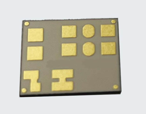
The ceramic capacitor PCB footprint refers to the specific layout design on a printed
circuit board (PCB) to accommodate a ceramic capacitor. It includes the arrangement
of the solder pads and other necessary features to ensure proper electrical and mechanical
connection between the ceramic capacitor and the PCB. The footprint may vary depending
on the specific package and size of the ceramic capacitor being used.
How to select ceramic capacitor pcb footprint?
To select the appropriate ceramic capacitor PCB footprint, you need to consider the following factors:
1. Capacitor package type: Ceramic capacitors come in various package types
such as surface mount (SMD) or through-hole. Determine the package type of the capacitor you are using.
2. Capacitor size: Ceramic capacitors are available in different sizes, such as 0402
, 0603, 0805, etc. The size will determine the dimensions of the PCB footprint.

3. Capacitance and voltage rating: Consider the required capacitance and
voltage rating for your application. These specifications may affect the size
and type of capacitor you choose, which in turn will impact the PCB footprint.
4. PCB design guidelines: Consult the datasheet or manufacturer’s guidelines f
or the recommended PCB footprint for the specific capacitor package you have
selected. The datasheet usually provides the recommended dimensions and layout
guidelines for the capacitor.
5. Manufacturing capabilities: Ensure that the selected PCB footprint is compatible
with your PCB manufacturing capabilities. Consider factors such as minimum trace
width and spacing, solder mask requirements, and manufacturing tolerances.
6. PCB assembly process: If you are using surface mount ceramic capacitors, make
sure the PCB footprint is compatible with your assembly process, including pick-and-place
machines and reflow soldering.