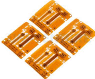
How to use pcb prototype board
Understanding The Basics Of PCB Prototype Boards
Printed Circuit Board (PCB) prototype boards are essential tools in the development and testing of electronic circuits. Understanding the basics of these boards is crucial for anyone involved in electronics design, whether a hobbyist or a professional engineer.
PCB prototype boards, often referred to as breadboards or perfboards, provide a platform for constructing and experimenting with circuit designs before committing to a final PCB layout. This process allows for the testing of circuit functionality, identification of potential issues, and refinement of design elements.
To begin with, it is important to recognize the different types of PCB prototype boards available.
Breadboards are typically used for temporary prototypes and are characterized by their grid of holes into which components can be inserted. These holes are connected in rows and columns, allowing for easy connections without soldering. On the other hand, perfboards, also known as stripboards, require soldering and are used for more permanent prototypes. They consist of a grid of holes with copper pads or strips on one side, enabling the creation of more robust connections.
When using a PCB prototype board, the first step is to plan the circuit layout.
This involves determining the placement of components and the routing of connections. It is advisable to sketch the circuit on paper or use software tools to visualize the design. This planning stage is crucial as it helps in identifying the optimal arrangement of components, minimizing the length of connections, and reducing potential interference or noise in the circuit.
Once the layout is planned, the next step is to place the components on the board.
For breadboards, components are inserted into the holes, and connections are made using jumper wires. It is important to ensure that connections are secure and that there is no unintentional contact between different parts of the circuit. For perfboards, components are placed on the non-copper side, and connections are made by soldering wires or using the copper strips to form conductive paths. Soldering requires precision and care to avoid short circuits or damage to components.
Testing the circuit is a critical phase in using a PCB prototype board.
After assembling the circuit, it is essential to verify its functionality by powering it on and measuring key parameters such as voltage, current, and signal integrity. This testing helps in identifying any discrepancies between the expected and actual performance of the circuit. If issues are detected, adjustments can be made by reconfiguring connections or replacing components as necessary.
Finally, once the prototype has been tested and refined, the design can be transferred to a permanent PCB for production.
This involves creating a schematic and layout using PCB design software, which can then be used to manufacture the final board. The prototype board serves as a valuable reference during this process, ensuring that the final product meets the desired specifications.
In conclusion, PCB prototype boards are indispensable in the electronics design process, offering a flexible and efficient means of developing and testing circuit designs. By understanding the basics of these boards and following a systematic approach to planning, assembling, and testing circuits, designers can effectively bring their electronic projects to fruition.

Step-By-Step Guide To Designing Your First PCB Prototype
Designing your first PCB prototype can be an exciting yet challenging endeavor. To begin, it is essential to understand the fundamental components and tools required for the process. A PCB prototype board, often referred to as a breadboard, serves as a preliminary model for testing and refining electronic circuits before mass production. This step-by-step guide will walk you through the process of designing your first PCB prototype, ensuring a smooth transition from concept to creation.
Initially, it is crucial to conceptualize your design by outlining the circuit you intend to build.
This involves sketching a schematic diagram, which serves as a blueprint for your PCB layout. Utilizing software tools such as Eagle, KiCad, or Altium Designer can significantly aid in this process, providing a digital platform to visualize and refine your circuit design. These tools offer libraries of components, allowing you to easily incorporate various elements into your schematic.
Once your schematic is complete, the next step involves transferring the design onto the PCB prototype board.
This process, known as layout design, requires careful consideration of component placement and routing. It is important to strategically position components to minimize signal interference and ensure efficient use of space. Additionally, paying attention to trace width and spacing is vital to prevent short circuits and ensure reliable performance.
After finalizing the layout, the next phase involves fabricating the PCB prototype.
This can be achieved through various methods, such as etching or milling. Etching involves using a chemical solution to remove unwanted copper from the board, leaving behind the desired circuit pattern. Alternatively, milling employs a CNC machine to mechanically remove excess material, creating the circuit traces. Both methods have their advantages and limitations, and the choice largely depends on available resources and personal preference.
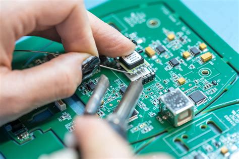
Following fabrication, the next step is assembling the components onto the PCB.
This involves soldering each component to its designated position on the board. It is essential to use the appropriate soldering techniques and tools to ensure secure connections and prevent damage to the components. A soldering iron with adjustable temperature settings, along with high-quality solder, can greatly enhance the assembly process.
Once assembly is complete, it is imperative to test the PCB prototype to verify its functionality.
This involves conducting a series of tests to ensure that the circuit operates as intended. Utilizing tools such as multimeters and oscilloscopes can aid in diagnosing any issues and validating the performance of the prototype. If discrepancies are identified, it may be necessary to revisit the design and make necessary adjustments.
Finally, after successful testing, the PCB prototype can be refined and prepared for mass production.
This may involve optimizing the design for cost-effectiveness and manufacturability, ensuring that the final product meets industry standards and specifications. Throughout this process, maintaining meticulous documentation is crucial, as it provides a comprehensive record of the design and development stages.
In conclusion, designing your first PCB prototype requires a methodical approach, from conceptualization to testing. By following these steps and utilizing the appropriate tools and techniques, you can successfully create a functional and reliable PCB prototype. This foundational experience not only enhances your understanding of electronic design but also paves the way for future innovations in the field.
Common Mistakes To Avoid When Using PCB Prototype Boards
When working with PCB prototype boards, it is crucial to be aware of common mistakes that can hinder the development process and compromise the functionality of the final product. Understanding these pitfalls and how to avoid them can significantly enhance the efficiency and success of your prototyping endeavors. One frequent mistake is neglecting to thoroughly plan the layout before beginning the assembly process. A well-thought-out design is essential to ensure that all components fit correctly and function as intended. Without a clear plan, you may encounter issues such as overlapping traces or insufficient space for components, which can lead to costly revisions and delays.
Another common error is the improper handling of components and the board itself.
Static electricity can damage sensitive electronic components, so it is vital to use anti-static wrist straps and mats when working with PCB prototype boards. Additionally, handling components with bare hands can introduce oils and contaminants that may affect their performance. Using tweezers or other appropriate tools can help prevent these issues. Furthermore, it is important to ensure that all components are correctly oriented and securely soldered to the board. Misaligned or loose components can cause short circuits or intermittent connections, leading to unreliable performance.
Transitioning to the next point, inadequate testing is another mistake that can have significant repercussions.
It is essential to test the prototype thoroughly at each stage of development to identify and rectify any issues early on. Skipping or rushing through the testing phase can result in undetected faults that may be more challenging and costly to fix later. Employing a systematic testing approach, including visual inspections, continuity tests, and functional tests, can help ensure that the prototype operates as expected.
Moreover, overlooking the importance of documentation is a mistake that can complicate future iterations or troubleshooting efforts.
Keeping detailed records of the design process, including schematics, component lists, and any modifications made, is invaluable for reference and communication with team members or collaborators. Proper documentation can also facilitate a smoother transition from prototype to production, as it provides a clear blueprint for manufacturing.
In addition to these considerations, it is crucial to be mindful of the limitations of the prototype board itself.
PCB prototype boards are typically designed for testing and development purposes and may not be suitable for high-frequency or high-power applications. Pushing the board beyond its intended capabilities can result in performance issues or even damage. Therefore, it is important to understand the specifications and constraints of the board and design your prototype accordingly.
Finally, failing to consider the thermal management of the prototype can lead to overheating and potential failure.
Components that generate significant heat may require additional cooling measures, such as heat sinks or fans, to maintain optimal performance. Ignoring thermal considerations can not only affect the functionality of the prototype but also reduce the lifespan of the components.
In conclusion, by being aware of these common mistakes and taking proactive steps to avoid them, you can enhance the success of your PCB prototyping projects. Careful planning, proper handling, thorough testing, meticulous documentation, and consideration of board limitations and thermal management are all critical factors in achieving a functional and reliable prototype. By addressing these areas, you can streamline the development process and increase the likelihood of a successful transition from prototype to production.
Tips For Testing And Troubleshooting PCB Prototypes
When working with PCB prototype boards, testing and troubleshooting are crucial steps in ensuring the functionality and reliability of your design. To begin with, it is essential to have a clear understanding of the circuit design and the intended functionality of the prototype. This foundational knowledge will guide you through the testing process and help you identify any discrepancies between the expected and actual performance of the board. Before powering up the prototype, a thorough visual inspection is recommended. This involves checking for any visible defects such as solder bridges, missing components, or incorrect component placement. These issues can often be rectified easily if identified early, thus preventing potential damage to the board or components.
Once the visual inspection is complete, the next step is to perform a continuity test.
This test ensures that all connections on the board are intact and that there are no unintended short circuits. Using a multimeter, you can verify that each trace on the PCB is connected as per the design. This step is particularly important in complex circuits where multiple layers and numerous connections are involved. After confirming continuity, it is advisable to conduct a power-on test. During this phase, apply power to the board while monitoring the current draw. An unexpected increase in current could indicate a short circuit or a component failure. It is crucial to address any anomalies immediately to prevent further damage.
Transitioning to functional testing, it is important to verify that each section of the circuit operates as intended.
This can be achieved by applying test signals and measuring the output at various points on the board. Oscilloscopes and logic analyzers are invaluable tools for this purpose, allowing you to visualize signal waveforms and ensure they match the expected behavior. If discrepancies are observed, it may be necessary to revisit the design or check for component malfunctions. In addition to functional testing, thermal analysis is another critical aspect of troubleshooting PCB prototypes. Excessive heat can lead to component failure and reduced lifespan of the board. Using thermal cameras or infrared thermometers, you can identify hotspots on the board and take corrective measures, such as improving heat dissipation or adjusting component placement.
Furthermore, it is beneficial to perform stress testing to evaluate the board’s performance under extreme conditions.
This involves subjecting the prototype to variations in temperature, humidity, and voltage to ensure it can withstand real-world operating environments. Stress testing can reveal weaknesses in the design that may not be apparent under normal conditions. Throughout the testing and troubleshooting process, maintaining detailed documentation is essential. Recording test results, observations, and any modifications made to the prototype will provide valuable insights for future iterations of the design. This documentation can also serve as a reference for identifying recurring issues and implementing long-term solutions.
In conclusion, testing and troubleshooting PCB prototypes require a methodical approach and attention to detail.
By conducting thorough inspections, continuity tests, functional evaluations, thermal analyses, and stress tests, you can ensure the reliability and performance of your design. Moreover, maintaining comprehensive documentation will facilitate continuous improvement and innovation in your PCB development projects. Through these practices, you can confidently advance from prototype to production, knowing that your design has been rigorously validated.


