Key Components in Functional PCB Testing
Introduction
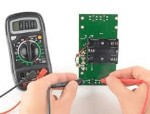
Printed Circuit Boards (PCBs) are the backbone of modern electronics, found in everything from consumer gadgets to industrial machinery. Ensuring their functionality is critical, and functional PCB testing plays a pivotal role in verifying that a PCB operates as intended before deployment. This process involves checking electrical performance, signal integrity, and overall reliability.
Several key components are essential in functional PCB testing, each contributing to the accuracy and efficiency of the process. This article explores these critical elements, including test fixtures, automated test equipment (ATE), boundary scan systems, oscilloscopes, and more.
1. Test Fixtures
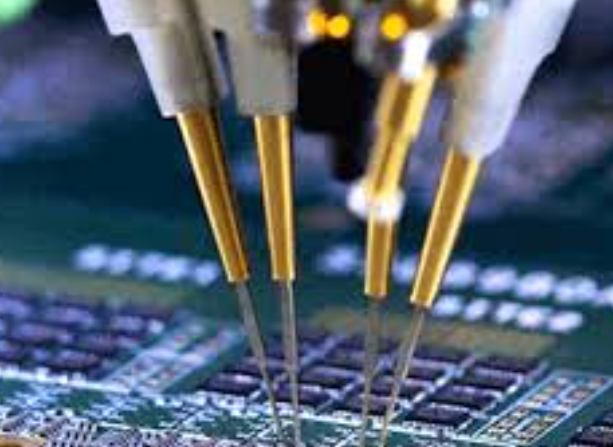
Test fixtures, also known as test jigs or beds-of-nails fixtures, are mechanical structures that hold the PCB in place during testing. They interface with the PCB’s test points, allowing test equipment to send and receive signals.
Types of Test Fixtures:
- Bed-of-Nails Fixtures: Use spring-loaded pogo pins to make electrical contact with test points.
- Flying Probe Fixtures: Use movable probes to test PCBs without custom fixtures, ideal for low-volume production.
- Vacuum Fixtures: Secure the PCB using suction, ensuring proper contact between test probes and the board.
Importance:
- Enable repeatable and consistent testing.
- Reduce human error by automating probe placement.
- Support high-speed testing in mass production.
2. Automated Test Equipment (ATE)
ATE systems are computer-controlled devices that perform functional tests on PCBs with minimal human intervention. They are widely used in high-volume manufacturing.
Key Features:
- Programmable Test Sequences: Allow engineers to define test procedures.
- High-Speed Testing: Capable of testing multiple PCBs per minute.
- Data Logging: Record test results for quality control and traceability.
Common ATE Components:
- Digital Signal Processors (DSPs): Analyze digital signals for correctness.
- Power Supplies: Provide stable voltage and current for testing.
- Relay Matrices: Route signals to different parts of the PCB.
Importance:
- Improve testing throughput.
- Reduce labor costs.
- Enhance test accuracy and repeatability.
3. Boundary Scan (JTAG) Testing
Boundary scan testing, based on the IEEE 1149.1 (JTAG) standard, is a method for testing interconnections on PCBs without physical probes.
How It Works:
- Uses dedicated test cells embedded in ICs.
- Allows testing of solder joints, shorts, and opens.
- Particularly useful for high-density boards with limited test access.
Importance:
- Enables testing of complex, multilayer PCBs.
- Reduces dependency on physical test points.
- Supports debugging and programming of onboard chips.
4. Oscilloscopes and Signal Analyzers
Oscilloscopes are essential for analyzing signal integrity, noise, and timing issues in PCBs.
Types:
- Digital Storage Oscilloscopes (DSOs): Capture and store waveforms for analysis.
- Mixed-Signal Oscilloscopes (MSOs): Combine analog and digital signal analysis.
- High-Speed Oscilloscopes: Used for high-frequency signal testing.
Key Applications:
- Verifying clock signals.
- Detecting signal distortions and crosstalk.
- Measuring rise/fall times and jitter.
Importance:
- Ensures signal integrity in high-speed designs.
- Helps diagnose intermittent faults.
- Supports compliance testing (e.g., EMI/EMC).
5. In-Circuit Testers (ICT)
ICT systems verify individual components on a PCB by checking resistance, capacitance, and other parameters.
Key Capabilities:
- Component Verification: Detects wrong or misaligned parts.
- Short/Open Detection: Identifies manufacturing defects.
- Functional Testing: Confirms basic operational behavior.
Importance:
- Catches defects early in production.
- Reduces rework costs.
- Improves overall product reliability.
6. Power Supplies and Load Boards
Stable power delivery is crucial for functional PCB testing. Programmable power supplies and load boards simulate real-world operating conditions.
Key Functions:
- Voltage/Current Regulation: Ensure the PCB receives correct power levels.
- Load Simulation: Mimics actual circuit loads for stress testing.
- Overcurrent/Overvoltage Protection: Prevents damage during testing.
Importance:
- Validates power distribution networks.
- Tests PCB behavior under different load conditions.
- Ensures compliance with power specifications.
7. Environmental Test Chambers
Some PCBs must operate in harsh conditions, requiring environmental stress testing.
Testing Methods:
- Temperature Cycling: Tests performance under extreme heat/cold.
- Humidity Testing: Checks moisture resistance.
- Vibration Testing: Simulates mechanical stress.
Importance:
- Ensures reliability in real-world conditions.
- Identifies potential failure modes.
- Supports military, automotive, and aerospace applications.
Conclusion
Functional PCB testing is a multi-faceted process that relies on several key components, each playing a critical role in ensuring PCB reliability and performance. From test fixtures and ATE systems to boundary scan and oscilloscopes, these tools help manufacturers detect defects, verify functionality, and improve product quality.
As PCBs become more complex, advancements in testing technologies will continue to evolve, further enhancing the efficiency and accuracy of functional PCB testing. Investing in the right testing infrastructure is essential for delivering high-quality electronic products in today’s competitive market.


