Live Circuit Testing in PCB Repair: Techniques and Best Practices
Introduction
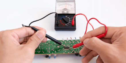
Printed Circuit Board (PCB) repair is a critical skill in electronics maintenance, ensuring the longevity and functionality of electronic devices. One of the most effective methods for diagnosing faults in PCBs is live circuit testing, also known as hot testing or powered-on testing. Unlike traditional offline testing methods (where the PCB is disconnected from power), live circuit testing allows technicians to measure voltages, currents, and signals while the circuit is operational.
This article explores the principles, techniques, tools, safety precautions, and best practices for live circuit testing in PCB repair.
1. Understanding Live Circuit Testing
Live circuit testing involves measuring electrical parameters on a powered PCB to identify faults such as short circuits, open traces, defective components, or incorrect voltage levels. Since the circuit is active, technicians can observe real-time behavior, making it easier to pinpoint intermittent or dynamic failures that may not appear during offline testing.
Advantages of Live Testing:
- Detects intermittent faults that occur only under power.
- Helps verify voltage regulation and power supply stability.
- Allows signal tracing in analog and digital circuits.
- Facilitates dynamic testing of components like transistors, ICs, and oscillators.
Disadvantages & Risks:
- Electrical hazards (risk of shock or short circuits).
- Potential for damaging sensitive components if probes slip.
- Requires proper grounding to avoid false readings.
2. Essential Tools for Live Circuit Testing
To perform live testing safely and effectively, technicians use specialized tools:
a. Digital Multimeter (DMM)
- Measures voltage (AC/DC), current, resistance, and continuity.
- Used to check power rails, component voltages, and signal levels.
b. Oscilloscope
- Captures waveforms and transient signals.
- Ideal for diagnosing analog circuits, clock signals, and noise issues.
c. Logic Analyzer
- Used in digital circuits to monitor data buses, serial communications, and logic levels.
d. Thermal Camera or Infrared Thermometer
- Detects overheating components (e.g., shorted ICs or failing regulators).
e. Non-Contact Voltage Detector
- Ensures safety by detecting live voltage before probing.
f. Isolation Transformer
- Protects the technician and equipment by isolating the PCB from mains voltage.
3. Key Techniques in Live PCB Testing
a. Voltage Measurements
- Power Rails Check: Verify VCC, GND, and regulated voltages (e.g., 3.3V, 5V, 12V).
- Component-Level Testing: Measure voltages across transistors, diodes, and IC pins (compare with datasheet values).
- Signal Tracing: Follow a signal path to locate breaks or distortions.
b. Current Measurements
- Use a clamp meter or DMM in series to measure current draw.
- High current may indicate a short circuit; low current may suggest an open circuit.
c. Signal Integrity Testing
- Use an oscilloscope to check:
- Clock signals (frequency, amplitude).
- Data lines (noise, distortion).
- PWM signals (duty cycle).
d. In-Circuit Component Testing
- Diodes & Transistors: Check forward/reverse bias in live conditions.
- Capacitors: Look for ripple voltage (bad capacitors show excessive noise).
- ICs: Monitor input/output pins for expected logic levels.
e. Thermal Analysis
- A hot component may indicate a short or overload.
- A cold component may be open or not receiving power.
4. Safety Precautions for Live Testing
Working on live circuits carries risks, so follow these safety guidelines:
a. Personal Safety
- Wear insulated gloves and safety glasses.
- Use one-handed probing to avoid accidental shocks.
- Keep the work area dry and well-lit.
b. Equipment Safety
- Use isolated power supplies or an isolation transformer.
- Avoid ground loops by ensuring proper grounding.
- Never short-circuit probes accidentally.
c. PCB Protection
- Use anti-static mats and wrist straps.
- Avoid slipping probes (can damage tiny traces).
- Discharge large capacitors before handling.
5. Step-by-Step Live Testing Procedure
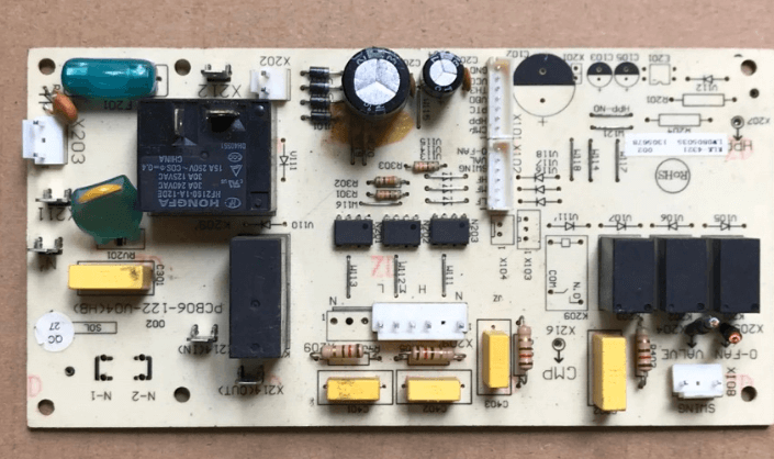
Step 1: Visual Inspection
- Look for burnt components, broken traces, or swollen capacitors.
Step 2: Power-On Check
- Apply power and check for smoke, sparks, or abnormal heating.
Step 3: Voltage Measurements
- Measure input voltage, regulator outputs, and critical IC voltages.
Step 4: Signal Tracing
- Use an oscilloscope to follow signals from input to output.
Step 5: Component-Level Diagnosis
- Test suspect components (transistors, diodes, ICs) in-circuit.
Step 6: Compare with Known Good Values
- Refer to schematics or datasheets for expected readings.
Step 7: Isolate Faults
- If a short is detected, use the half-splitting method to narrow it down.
6. Common Faults Detected by Live Testing
| Fault Type | Symptoms | Diagnostic Method |
|---|---|---|
| Short Circuit | Excessive current, overheating | Thermal imaging, resistance check |
| Open Circuit | No voltage, signal loss | Continuity test, voltage tracing |
| Incorrect Voltage | Low/high readings | DMM measurement |
| Noisy Power Supply | Ripple on oscilloscope | Capacitor check, regulator test |
| Failing IC | Wrong logic levels, overheating | Logic analyzer, voltage check |
7. Best Practices for Effective Live Testing
- Work Methodically – Follow a structured approach.
- Document Measurements – Record voltages for comparison.
- Use Proper Grounding – Avoid false readings from floating grounds.
- Start with Low Voltage – Gradually increase power to avoid damage.
- Verify Before Replacement – Ensure a component is faulty before desoldering.
8. Conclusion
Live circuit testing is an indispensable technique in PCB repair, allowing technicians to diagnose faults efficiently while the circuit is operational. By using tools like multimeters, oscilloscopes, and thermal cameras—and following strict safety protocols—repair professionals can accurately identify issues ranging from power supply failures to signal integrity problems.
Mastering live testing requires practice, precision, and patience, but it significantly enhances the ability to troubleshoot complex PCB faults. Whether repairing consumer electronics, industrial control systems, or aerospace circuits, live measurement techniques remain a cornerstone of effective electronics diagnostics.