Metal core pcb design guide
Understanding The Basics Of Metal Core PCB Design
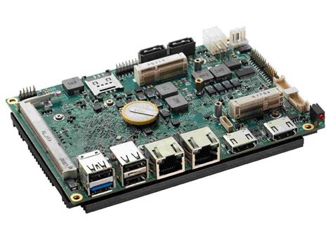
Metal core printed circuit boards (PCBs) have become increasingly popular in various industries due to their superior thermal management capabilities. Understanding the basics of metal core PCB design is essential for engineers and designers who aim to leverage these benefits in their applications. At the heart of metal core PCBs is the metal substrate, typically aluminum or copper, which serves as the foundation for the circuit. This metal core is sandwiched between layers of dielectric material and copper circuitry, providing a robust structure that efficiently dissipates heat away from critical components.
The choice of metal substrate is a crucial consideration in the design process.
Aluminum is often favored for its balance of cost-effectiveness and thermal conductivity, making it suitable for a wide range of applications. Copper, on the other hand, offers superior thermal performance but at a higher cost, making it ideal for high-power applications where heat dissipation is paramount. The thickness of the metal core also plays a significant role in thermal management, with thicker cores providing better heat dissipation but potentially increasing the overall weight and cost of the PCB.
Transitioning to the dielectric layer, its primary function is to electrically insulate the metal core from the copper circuitry while facilitating efficient heat transfer.
The thermal conductivity of the dielectric material is a critical parameter, as it directly impacts the PCB’s ability to manage heat. Materials with higher thermal conductivity are preferred, as they allow for more effective heat transfer from the components to the metal core. Additionally, the dielectric layer must possess adequate electrical insulation properties to prevent short circuits and ensure the reliability of the PCB.
The copper circuitry layer is where the electrical connections are established, and its design is pivotal in determining the overall performance of the PCB.
The thickness of the copper layer can vary depending on the current-carrying requirements of the application. Thicker copper layers can handle higher currents but may also increase the cost and complexity of the manufacturing process. Therefore, designers must carefully balance these factors to achieve an optimal design.
Incorporating thermal vias is another important aspect of metal core PCB design.
These vias are strategically placed to facilitate the transfer of heat from the surface-mounted components to the metal core. By optimizing the placement and size of thermal vias, designers can significantly enhance the thermal performance of the PCB, ensuring that heat is efficiently dissipated and preventing potential overheating issues.
Moreover, the layout of components on a metal core PCB requires careful consideration.
Components that generate significant heat should be placed in proximity to the metal core to maximize heat dissipation. Additionally, the use of thermal interface materials (TIMs) can further improve thermal conductivity between components and the metal core, enhancing the overall thermal management of the PCB.
In conclusion, understanding the basics of metal core PCB design involves a comprehensive consideration of various factors, including the choice of metal substrate, dielectric material, copper circuitry, and thermal management techniques. By carefully balancing these elements, designers can create PCBs that not only meet the electrical and mechanical requirements of their applications but also excel in thermal performance. As industries continue to demand more efficient and reliable electronic solutions, the role of metal core PCBs in meeting these challenges is set to grow, making a solid understanding of their design principles increasingly important.
Key Advantages Of Using Metal Core PCBs In Electronics
Metal Core Printed Circuit Boards (MCPCBs) have emerged as a pivotal innovation in the electronics industry, offering a range of advantages that make them an attractive choice for various applications. These PCBs are distinguished by their use of a metal core, typically aluminum, copper, or a mixture of special alloys, which serves as a thermal management solution. This unique construction provides several key benefits that enhance the performance and reliability of electronic devices.
One of the primary advantages of using metal core PCBs is their superior thermal conductivity.
In electronic devices, heat dissipation is a critical factor that can significantly impact performance and longevity. Traditional PCBs, often made from materials like FR-4, can struggle to efficiently dissipate heat, leading to potential overheating and failure of components. In contrast, the metal core in MCPCBs acts as a heat sink, effectively drawing heat away from critical components and distributing it across the board. This enhanced thermal management capability ensures that devices can operate at optimal temperatures, thereby improving their reliability and extending their lifespan.
Moreover, metal core PCBs offer improved mechanical stability compared to their non-metal counterparts.
The metal core provides a robust foundation that enhances the structural integrity of the board, making it less susceptible to warping and mechanical stress. This is particularly beneficial in applications where the PCB is exposed to harsh environmental conditions or mechanical vibrations. The increased durability of MCPCBs ensures that they can withstand such challenges without compromising performance, making them ideal for use in automotive, aerospace, and industrial applications.
In addition to thermal and mechanical advantages, metal core PCBs also contribute to enhanced electrical performance.
The metal core can serve as a ground plane, reducing electromagnetic interference (EMI) and improving signal integrity. This is especially important in high-frequency applications where signal clarity is paramount. By minimizing EMI, MCPCBs help maintain the integrity of the signals being transmitted, ensuring accurate and reliable communication between components.
Furthermore, the use of metal core PCBs can lead to a reduction in the overall size and weight of electronic devices.
The efficient heat dissipation properties of MCPCBs allow for the use of smaller heat sinks and cooling mechanisms, which can contribute to more compact and lightweight designs. This is a significant advantage in industries such as consumer electronics and telecommunications, where there is a constant demand for smaller, more portable devices.
While the benefits of metal core PCBs are numerous, it is important to consider the potential challenges associated with their use.
The manufacturing process for MCPCBs can be more complex and costly compared to traditional PCBs, due to the need for specialized equipment and materials. However, the long-term advantages in terms of performance, reliability, and design flexibility often outweigh these initial costs, making MCPCBs a worthwhile investment for many applications.
In conclusion, metal core PCBs offer a range of advantages that make them an invaluable component in modern electronics. Their superior thermal management, mechanical stability, and electrical performance provide significant benefits that enhance the functionality and reliability of electronic devices. As technology continues to advance, the demand for efficient and reliable PCBs will only grow, solidifying the role of metal core PCBs as a key player in the future of electronics design.
Step-By-Step Guide To Designing A Metal Core PCB
Designing a metal core printed circuit board (MCPCB) involves a series of meticulous steps that ensure optimal performance and reliability, particularly in applications where heat dissipation is critical. The process begins with understanding the unique properties of metal core PCBs, which are distinct from traditional PCBs due to their metal substrate, typically aluminum or copper. This substrate provides superior thermal conductivity, making MCPCBs ideal for high-power applications such as LED lighting, power converters, and automotive electronics.
The first step in designing a metal core PCB is to define the requirements of the project.
This involves determining the electrical and thermal performance needs, as well as the mechanical constraints of the application. By clearly outlining these parameters, designers can make informed decisions about the materials and layout of the PCB. Once the requirements are established, the next step is to select the appropriate materials. The choice of metal core material is crucial, as it directly impacts the thermal management capabilities of the PCB. Aluminum is commonly used due to its balance of cost and thermal performance, while copper offers superior thermal conductivity at a higher price point.
With the materials selected, the design process moves to the schematic and layout phase.
During this stage, designers create a detailed schematic that outlines the electrical connections and components of the PCB. It is essential to consider the thermal paths and ensure that heat-generating components are strategically placed to maximize heat dissipation. The layout should also account for the mechanical properties of the metal core, ensuring that the board can withstand the physical stresses of its intended application.
Transitioning from the schematic to the physical design, designers must pay close attention to the stack-up configuration.
The stack-up refers to the arrangement of the various layers of the PCB, including the metal core, dielectric layer, and copper traces. The dielectric layer, which electrically insulates the metal core from the copper traces, must be carefully selected to provide adequate thermal conductivity while maintaining electrical insulation. The thickness of this layer can significantly affect the thermal performance of the PCB, so it must be chosen with precision.
As the design progresses, thermal analysis becomes a critical step.
Using simulation software, designers can model the thermal behavior of the PCB under various operating conditions. This analysis helps identify potential hotspots and allows for adjustments to the layout or material selection to improve thermal management. By iterating on the design based on these simulations, designers can optimize the PCB for both performance and reliability.
Once the design is finalized, the next step is to prepare the manufacturing files.
These files, typically in Gerber format, contain all the necessary information for fabricating the PCB, including the layout, drill holes, and layer stack-up. It is crucial to review these files thoroughly to ensure accuracy and completeness before sending them to a manufacturer.
Finally, after the PCB is manufactured, it undergoes a series of tests to verify its performance and reliability. These tests may include electrical testing, thermal cycling, and mechanical stress testing, depending on the application requirements. By following this step-by-step guide, designers can create metal core PCBs that meet the demanding needs of modern electronic applications, ensuring both efficiency and durability.
Common Challenges And Solutions In Metal Core PCB Design
Designing metal core printed circuit boards (PCBs) presents a unique set of challenges that require careful consideration and innovative solutions. As the demand for high-performance electronic devices continues to grow, metal core PCBs have become increasingly popular due to their superior thermal management capabilities. However, the integration of metal cores into PCB design introduces complexities that must be addressed to ensure optimal functionality and reliability.
One of the primary challenges in metal core PCB design is managing thermal expansion.
Unlike traditional PCBs, metal core PCBs incorporate a metal layer, typically aluminum or copper, which has a different coefficient of thermal expansion compared to the dielectric materials used. This discrepancy can lead to mechanical stress and potential delamination during thermal cycling. To mitigate this issue, designers often employ materials with matched thermal expansion properties or incorporate flexible interconnects that can absorb the stress. Additionally, careful selection of the metal core thickness and the use of thermal vias can further enhance thermal management while minimizing expansion-related issues.
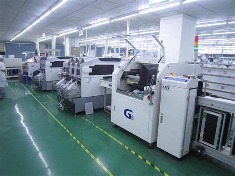
Another significant challenge is the complexity of the manufacturing process.
Metal core PCBs require specialized fabrication techniques, such as drilling and plating through metal layers, which can increase production costs and time. To address these challenges, collaboration with experienced manufacturers is crucial. By leveraging their expertise, designers can optimize the layout and stack-up of the PCB to reduce manufacturing complexities. Furthermore, employing advanced simulation tools during the design phase can help identify potential manufacturing issues early, allowing for adjustments before production begins.
Signal integrity is also a critical concern in metal core PCB design.
The presence of a metal core can introduce electromagnetic interference (EMI) and affect signal propagation. To overcome this, designers must carefully plan the placement of signal traces and ground planes. Utilizing differential signaling and proper grounding techniques can significantly reduce EMI and improve signal integrity. Additionally, incorporating shielding layers and using high-frequency laminates can further enhance performance by minimizing signal loss and crosstalk.
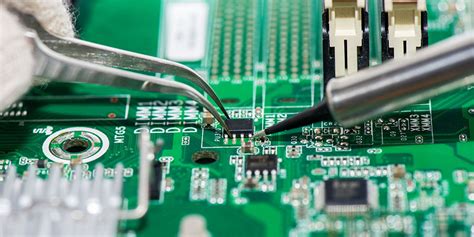
Moreover, the integration of components on metal core PCBs poses its own set of challenges.
The metal core can act as a heat sink, which is beneficial for thermal management but can complicate the soldering process. The high thermal conductivity of the metal can lead to uneven heat distribution during soldering, resulting in poor solder joints. To address this, designers often use thermal relief pads and preheat the board to ensure even heat distribution. Additionally, selecting solder materials with appropriate melting points and employing controlled reflow profiles can enhance solder joint quality.
Finally, cost considerations cannot be overlooked in metal core PCB design.
The use of metal cores and specialized manufacturing processes can increase the overall cost of production. To manage costs effectively, designers should conduct a thorough cost-benefit analysis during the design phase. This involves evaluating the trade-offs between performance requirements and budget constraints. By optimizing the design for manufacturability and exploring alternative materials or processes, it is possible to achieve a balance between performance and cost.
In conclusion, while metal core PCB design presents several challenges, these can be effectively addressed through careful planning and collaboration with experienced manufacturers. By understanding the intricacies of thermal management, manufacturing processes, signal integrity, component integration, and cost considerations, designers can create high-performance metal core PCBs that meet the demands of modern electronic applications. Through innovative solutions and strategic design choices, the potential of metal core PCBs can be fully realized, paving the way for more efficient and reliable electronic devices.


