PCB Design Electrical Rule Checker: Solving DRC Issues in Modern Electronics
Introduction to DRC in PCB Design
In the world of printed circuit board (PCB) design, Design Rule Checking (DRC) has become an indispensable part of the development process. Electrical Rule Checkers, specifically designed to identify and resolve DRC issues, have evolved into sophisticated tools that ensure PCB designs meet both manufacturability and performance requirements before proceeding to production.
DRC tools serve as the final quality gate before a PCB design moves to fabrication, verifying that the design complies with a set of predefined rules that encompass electrical, physical, and manufacturing constraints. The importance of these tools has grown exponentially as PCBs have become more complex, with higher component densities, faster signal speeds, and more stringent reliability requirements.
Modern electrical rule checkers go beyond simple spacing and clearance verification, incorporating advanced checks for signal integrity, power integrity, electromagnetic compatibility (EMC), and thermal performance. This article explores how contemporary DRC tools identify and help resolve various types of design rule violations throughout the PCB development cycle.
The Evolution of PCB Design Rule Checking
The concept of design rule checking originated in the semiconductor industry in the 1970s before being adopted by PCB design tools. Early DRC systems were rudimentary, primarily checking for basic spacing violations and connection errors. Today’s electrical rule checkers represent decades of refinement and technological advancement.
Modern DRC systems have evolved in several key aspects:
- Rule Complexity: From simple spacing rules to complex electrical constraints like differential pair matching, impedance control, and return path verification.
- Integration: Tight integration with schematic capture, layout tools, and simulation environments creates a seamless design flow.
- Automation: Advanced algorithms can automatically correct certain types of violations or suggest multiple resolution options.
- Customization: Designers can create custom rule sets tailored to specific technologies or company standards.
- Real-time Feedback: Many systems now provide immediate feedback during layout rather than waiting for a final batch check.
This evolution has been driven by the increasing challenges of modern electronics design, where high-speed digital circuits, sensitive analog components, and RF elements must coexist on increasingly compact boards.
Common DRC Violations and Their Electrical Implications
Understanding common DRC violations helps designers anticipate and prevent issues early in the design process. Here are some of the most frequent electrical-related DRC problems:
Clearance and Creepage Violations
These violations occur when conductive elements (traces, pads, vias) are placed too close together, potentially leading to:
- Electrical Shorts: Particularly concerning in high-voltage designs or boards exposed to contaminants.
- Signal Crosstalk: Unwanted coupling between adjacent signals in high-speed designs.
- Manufacturing Defects: Tight spacing may exceed fabrication capabilities, leading to etching problems.
Modern rule checkers can differentiate between various voltage levels and adjust clearance requirements accordingly.
Impedance Mismatches
With high-speed designs, maintaining consistent impedance is crucial for signal integrity. DRC tools check:
- Trace width deviations that affect characteristic impedance
- Improper reference plane transitions
- Inadequate return paths for high-frequency signals
Power Delivery Issues
Electrical rule checkers identify problems in power distribution networks:
- Insufficient trace widths for current carrying capacity
- Missing or inadequate decoupling capacitors
- Excessive voltage drop across power rails
- Improper power plane segmentation
Electromagnetic Compatibility (EMC) Concerns
Advanced DRC systems incorporate checks to prevent EMC problems:
- Inadequate shielding of sensitive circuits
- Poor high-frequency signal routing practices
- Improper grounding strategies
- Antenna-like structures that may radiate unintentionally
Advanced Features of Modern Electrical Rule Checkers
Contemporary DRC tools offer sophisticated capabilities that go beyond basic rule verification:
Constraint Management Systems
Modern PCB design tools incorporate comprehensive constraint managers that:
- Allow hierarchical rule definition (board-level to net-level)
- Support complex conditional rules (e.g., different spacing for high-voltage nets)
- Enable 3D design rule checking for components and mechanical integration
Real-time DRC Feedback
Instead of waiting for a batch DRC run, many tools now provide:
- Continuous design rule verification during layout
- Visual indicators of violations (highlighting, overlays)
- Tooltips with violation details and suggested fixes
Automated Correction Suggestions
Advanced systems can:
- Propose multiple solutions for each violation
- Automatically implement selected fixes (e.g., pushing traces apart)
- Maintain design intent while resolving violations
Manufacturing-Aware Checking
Integration with fabrication capabilities allows:
- Rule sets tailored to specific manufacturers’ capabilities
- DFM (Design for Manufacturing) rule checking
- Panelization and assembly-related checks
Implementing an Effective DRC Strategy
To maximize the benefits of electrical rule checking, designers should adopt a systematic approach:
1. Rule Set Development
- Start with industry standards (IPC, etc.) as a baseline
- Incorporate manufacturer-specific capabilities
- Add company-specific design practices
- Include product-specific requirements (high-voltage, RF, etc.)
2. Phased Verification Approach
- Schematic-level electrical rules checking
- Initial layout DRC with basic rules
- Intermediate DRC with increasing rule strictness
- Final comprehensive DRC before release
3. DRC Result Analysis and Triage
- Categorize violations by severity
- Distinguish between must-fix and waiver-able violations
- Document design decisions for exception cases
4. Continuous Rule Set Refinement
- Update rules based on manufacturing feedback
- Incorporate lessons learned from test failures
- Adapt to new technologies and design challenges
Case Studies: DRC Solving Real-World Problems
High-Speed Digital Design
A networking equipment manufacturer reduced signal integrity issues by 60% after implementing advanced DRC rules for:
- Strict impedance control on critical nets
- Length matching requirements for parallel buses
- Proper reference plane continuity checking
Power Electronics Application
An electric vehicle component supplier eliminated field failures by enhancing their DRC to include:
- Voltage-dependent clearance rules
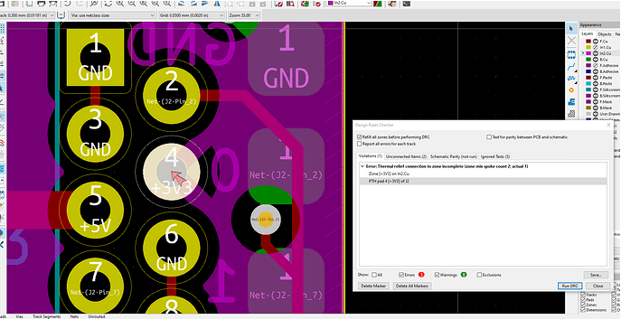
- Thermal relief verification for high-current connections
- Creepage distance checking for moisture resistance
Consumer Electronics Miniaturization
A smartphone manufacturer achieved first-pass success on complex 12-layer HDI boards by:
- Implementing microvia-specific DRC rules
- Adding rules for solder mask webbing between fine-pitch components
- Incorporating 3D component clearance checking
Future Trends in PCB Electrical Rule Checking
The evolution of DRC tools continues with several emerging trends:
AI-Assisted DRC
Machine learning algorithms are being applied to:
- Predict potential violations before they occur
- Suggest optimal routing solutions that avoid multiple violation types
- Learn from design histories to improve rule sets
Cloud-Based DRC Services
- Centralized rule set management across organizations
- Real-time collaboration on violation resolution
- Access to constantly updated manufacturer rule databases
3D Electromagnetic Rule Checking
As boards become more three-dimensional with embedded components and complex shielding:
- True 3D electromagnetic compliance checking
- Thermal and mechanical stress interaction analysis
- Combined PCB/enclosure EMC verification
Signoff-Quality DRC
The line between DRC and full verification is blurring with:
- Integrated signal/power integrity analysis
- Simultaneous switching noise prediction
- Comprehensive EMC pre-compliance checking
Conclusion
Electrical Rule Checking in PCB design has matured from simple spacing verification to a comprehensive design assurance methodology. Modern DRC tools not only identify problems but increasingly help solve them through advanced automation and intelligent suggestions.
As PCB technology continues to advance, with higher speeds, greater complexity, and more stringent reliability requirements, the role of electrical rule checking will only grow in importance. Design teams that implement robust DRC strategies and stay current with the latest verification technologies will maintain a competitive advantage through higher first-pass success rates, improved product reliability, and faster time-to-market.
The future of DRC lies in tighter integration with simulation, more intelligent automation, and expansion into new verification domains. However, the fundamental value remains the same: catching and resolving electrical issues early in the design process when they are easiest and least expensive to fix. In an industry where a single PCB respin can cost tens of thousands of dollars and weeks of delay, effective electrical rule checking remains one of the most valuable investments a design team can make.