PCB Electroplating Process: A Comprehensive Guide
Introduction
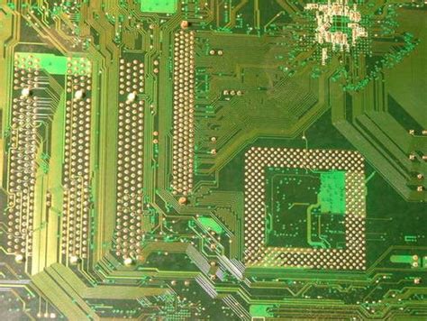
Printed Circuit Boards (PCBs) are the backbone of modern electronics, providing mechanical support and electrical connections for components. One of the critical steps in PCB manufacturing is the electroplating process, which deposits a thin layer of metal onto the board’s surface to enhance conductivity, corrosion resistance, and solderability. This article explores the PCB electroplating process in detail, covering its types, steps, challenges, and advancements.
1. Importance of Electroplating in PCB Manufacturing
Electroplating is essential for PCBs because it:
- Improves Conductivity: Ensures reliable electrical connections between layers.
- Enhances Durability: Protects copper traces from oxidation and corrosion.
- Facilitates Soldering: Provides a surface suitable for component attachment.
- Enables Fine Features: Allows for precise deposition in high-density interconnect (HDI) PCBs.
Without electroplating, PCBs would suffer from poor performance, reduced lifespan, and manufacturing defects.
2. Types of PCB Electroplating
Several electroplating techniques are used in PCB fabrication, each serving different purposes:
2.1 Copper Electroplating
- Purpose: Forms conductive traces and through-hole connections.
- Process: Copper ions in an electrolyte solution are deposited onto the PCB substrate via an electric current.
- Applications: Used for through-hole plating (PTH) and surface layer formation.
2.2 Gold Electroplating (Hard Gold & Soft Gold)
- Hard Gold: Contains nickel or cobalt for wear resistance (used in edge connectors).
- Soft Gold: Pure gold plating for wire bonding in semiconductor packaging.
- Advantages: Excellent conductivity and corrosion resistance.
2.3 Nickel Electroplating
- Purpose: Acts as a barrier layer between copper and gold/solder.
- Benefits: Prevents diffusion of copper into gold and improves solder joint reliability.
2.4 Silver Electroplating
- Used For: High-frequency applications due to low resistivity.
- Limitations: Prone to tarnishing, requiring additional protection.
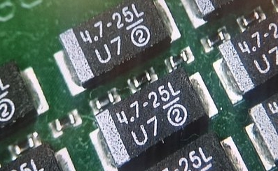
2.5 Tin Electroplating
- Commonly Used: As a solderable finish for surface mount technology (SMT).
- Advantages: Cost-effective and provides good solderability.
3. Step-by-Step PCB Electroplating Process
The electroplating process involves multiple stages to ensure uniform and high-quality metal deposition.
3.1 Surface Preparation
- Cleaning: Removes contaminants (dust, oils, oxides) using chemical cleaners.
- Microetching: Roughens the surface to improve adhesion (typically using sulfuric acid or sodium persulfate).
3.2 Activation
- Catalyst Application: A palladium-based solution activates non-conductive surfaces (for through-hole plating).
- Acceleration: Removes excess palladium to ensure uniform plating.
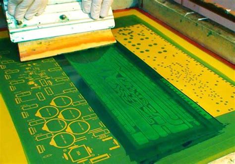
3.3 Electroplating Bath Setup
- Electrolyte Solution: Contains metal ions (e.g., copper sulfate for copper plating).
- Anode: Made of the plating metal (e.g., copper anode for copper plating).
- Cathode: The PCB itself, where metal deposition occurs.
3.4 Electroplating Parameters
- Current Density: Controlled to avoid uneven deposition (typically 1–5 A/dm²).
- Temperature: Affects deposition rate and quality (usually 20–30°C).
- Agitation: Ensures uniform ion distribution (mechanical or air agitation).
3.5 Post-Plating Treatments
- Rinsing: Removes residual chemicals.
- Drying: Prevents water spots or oxidation.
- Quality Inspection: Checks for thickness uniformity, adhesion, and defects.
4. Challenges in PCB Electroplating
Despite its importance, electroplating presents several challenges:
4.1 Uneven Deposition
- Causes: Poor current distribution, improper agitation.
- Solution: Optimize anode placement and use pulse plating techniques.
4.2 Plating Voids (In Through-Holes)
- Causes: Air bubbles, poor wetting, or insufficient catalyst activation.
- Solution: Improve hole wetting with surfactants and vacuum-assisted plating.
4.3 Overplating & Underplating
- Overplating: Excessive metal buildup leads to short circuits.
- Underplating: Insufficient metal causes weak connections.
- Solution: Monitor plating time and current density precisely.
4.4 Adhesion Issues
- Causes: Poor surface preparation or contamination.
- Solution: Ensure thorough cleaning and microetching.
5. Advances in PCB Electroplating Technology
Recent innovations have improved electroplating efficiency and quality:
5.1 Pulse Plating
- Uses alternating high/low current pulses for better deposition control.
- Reduces voids and improves uniformity.
5.2 Direct Metallization (Alternative to Electroless Copper)
- Eliminates formaldehyde-based electroless copper, making the process more environmentally friendly.
- Uses conductive polymers or carbon-based coatings.
5.3 High-Speed Electroplating
- Increases throughput for mass production.
- Requires advanced filtration and agitation systems.
5.4 Additive Manufacturing (3D PCB Plating)
- Enables selective plating for complex geometries.
- Useful for flexible and rigid-flex PCBs.
6. Environmental & Safety Considerations
Electroplating involves hazardous chemicals, requiring strict regulations:
- Wastewater Treatment: Neutralizes acids and removes heavy metals.
- Ventilation: Prevents exposure to toxic fumes.
- Alternative Chemistries: Adoption of greener plating solutions (e.g., non-cyanide gold plating).

7. Conclusion
The PCB electroplating process is a critical step in ensuring reliable and high-performance circuit boards. From copper deposition for conductivity to gold plating for corrosion resistance, each plating type serves a unique purpose. While challenges like uneven deposition and voids persist, advancements such as pulse plating and direct metallization continue to enhance the process. As PCB technology evolves toward finer pitches and higher densities, electroplating techniques must adapt to meet these demands while maintaining environmental sustainability.