PCB Laminate: Types, Properties, and Selection Criteria
Introduction
Printed Circuit Boards (PCBs) are the backbone of modern electronics, providing mechanical support and electrical connections for components. A critical component of PCBs is the laminate, which forms the substrate upon which conductive traces are etched. The choice of PCB laminate significantly impacts the performance, reliability, and cost of the final product.
This article explores the different types of PCB laminates, their key properties, and factors to consider when selecting the right material for a specific application.
1. What is PCB Laminate?
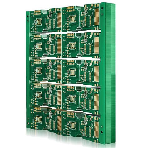
PCB laminate is a composite material consisting of a dielectric substrate (typically reinforced with fiberglass) and a conductive layer (usually copper). The substrate provides insulation and mechanical stability, while the copper layer forms the conductive pathways for electrical signals.
Key Components of PCB Laminate:
- Dielectric Substrate: Provides insulation and structural support (e.g., FR-4, polyimide, PTFE).
- Conductive Layer: Typically copper foil (electrodeposited or rolled annealed).
- Resin System: Binds the substrate together (e.g., epoxy, phenolic, cyanate ester).
- Reinforcement Material: Enhances mechanical strength (e.g., fiberglass, ceramic, Kevlar).
2. Types of PCB Laminates
2.1 FR-4 Laminate
FR-4 (Flame Retardant 4) is the most widely used PCB laminate due to its balance of performance, cost, and manufacturability.
- Composition: Woven fiberglass cloth with epoxy resin.
- Key Properties:
- Good mechanical strength
- Flame retardant (UL94-V0 rated)
- Moderate thermal resistance (~130°C Tg)
- Cost-effective
- Applications: Consumer electronics, industrial controls, automotive electronics.
2.2 High-Tg FR-4 Laminate
For applications requiring higher thermal stability, High-Tg FR-4 laminates are used.
- Glass Transition Temperature (Tg): 170°C–180°C
- Benefits:
- Better thermal performance for lead-free soldering
- Reduced warpage at high temperatures
- Applications: High-power electronics, automotive, aerospace.
2.3 Polyimide Laminate
Polyimide laminates are known for their excellent thermal and chemical resistance.
- Key Properties:
- High Tg (>250°C)
- Excellent flexibility (used in flex PCBs)
- Superior chemical resistance
- Disadvantages: Higher cost than FR-4
- Applications: Aerospace, military, flexible circuits.
2.4 PTFE (Teflon) Laminate
Polytetrafluoroethylene (PTFE) laminates are used in high-frequency applications due to their low dielectric loss.
- Key Properties:
- Extremely low dielectric constant (Dk ~2.1)
- Low dissipation factor (Df <0.001)
- Excellent high-frequency performance
- Disadvantages: Expensive, difficult to process
- Applications: RF/microwave circuits, 5G, radar systems.
2.5 Ceramic-Filled Laminates
These laminates incorporate ceramic particles to enhance thermal conductivity and stability.
- Key Properties:
- High thermal conductivity
- Low CTE (Coefficient of Thermal Expansion)
- Improved signal integrity at high frequencies
- Applications: High-power LED, power electronics, RF modules.
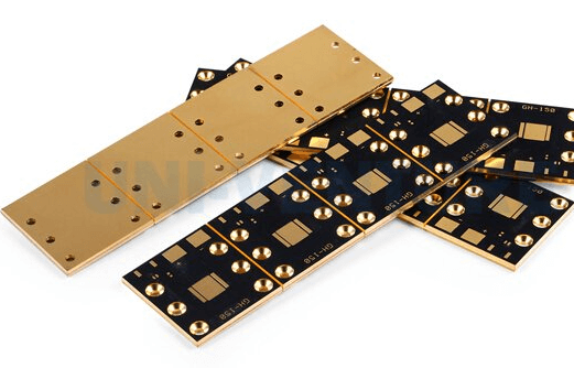
2.6 Metal-Core Laminates (MCPCBs)
Metal-core PCBs (MCPCBs) use a metal base (usually aluminum or copper) for superior heat dissipation.
- Key Properties:
- Excellent thermal management
- Used in high-power applications
- Applications: LED lighting, power converters, automotive electronics.

3. Key Properties of PCB Laminates
3.1 Dielectric Constant (Dk)
- Measures the material’s ability to store electrical energy.
- Lower Dk is better for high-speed signals (reduces signal delay).
3.2 Dissipation Factor (Df)
- Indicates signal loss due to dielectric heating.
- Critical for high-frequency applications (e.g., 5G, mmWave).
3.3 Glass Transition Temperature (Tg)
- The temperature at which the laminate changes from rigid to soft.
- Higher Tg improves thermal reliability.
3.4 Thermal Conductivity
- Important for heat dissipation in high-power PCBs.
- Metal-core and ceramic-filled laminates offer better thermal performance.
3.5 Coefficient of Thermal Expansion (CTE)
- Measures how much the laminate expands with temperature.
- A mismatch between PCB and components can cause reliability issues.
3.6 Moisture Absorption
- Some laminates (e.g., PTFE) absorb moisture, affecting performance.
- Low moisture absorption is critical for humid environments.
4. Selection Criteria for PCB Laminates
4.1 Electrical Requirements
- High-frequency applications: PTFE or ceramic-filled laminates (low Dk/Df).
- Standard digital circuits: FR-4 is sufficient.
4.2 Thermal Requirements
- High-power circuits: Metal-core or high-Tg laminates.
- Flexible PCBs: Polyimide for heat resistance.
4.3 Mechanical Requirements
- Rigid PCBs: FR-4, high-Tg FR-4.
- Flexible PCBs: Polyimide.
4.4 Cost Considerations
- FR-4 is the most cost-effective.
- PTFE and polyimide are expensive but necessary for specialized applications.
4.5 Environmental Conditions
- High humidity: Low moisture-absorption laminates.
- High-temperature environments: Polyimide or ceramic laminates.
5. Future Trends in PCB Laminates
- Low-Loss Materials for 5G/6G: Demand for ultra-low Df laminates is rising.
- Sustainable Laminates: Eco-friendly resins and recyclable materials.
- Advanced Thermal Management: Improved metal-core and ceramic laminates.
Conclusion
Selecting the right PCB laminate is crucial for ensuring performance, reliability, and cost-efficiency. FR-4 remains the industry standard, but specialized applications require advanced materials like polyimide, PTFE, or metal-core laminates. Engineers must consider electrical, thermal, mechanical, and environmental factors when choosing a laminate.
As technology evolves, new laminate materials will continue to emerge, enabling faster, more efficient, and more reliable PCBs for next-generation electronics.


