PCB Short Circuit Inspection Methods: A Comprehensive Guide
Printed Circuit Boards (PCBs) are the backbone of modern electronics, and any defect, especially a short circuit, can lead to equipment failure, overheating, or even fire hazards. Detecting and resolving PCB short circuits is crucial in manufacturing, testing, and troubleshooting. This article explores various methods for identifying PCB short circuits, including visual inspection, multimeter testing, thermal imaging, and advanced techniques like automated optical inspection (AOI) and X-ray inspection.
1. Introduction to PCB Short Circuits
A short circuit occurs when an unintended low-resistance path forms between two or more conductive traces, pads, or components, causing excessive current flow. Common causes include:
- Solder bridges (excess solder connecting adjacent traces)
- Damaged insulation (scratched or cracked PCB substrate)
- Component misplacement (incorrectly placed or soldered parts)
- Manufacturing defects (etching errors or copper remnants)
Short circuits can lead to:
- Overheating
- Component failure
- Power supply damage
- Complete PCB malfunction
To prevent these issues, effective inspection methods are essential.
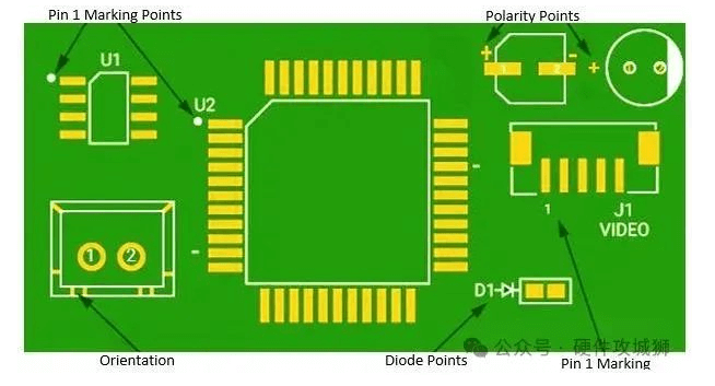
2. Visual Inspection
The simplest and most cost-effective method is manual visual inspection (MVI).
Steps for Visual Inspection:
- Use a magnifying glass or microscope to examine solder joints, traces, and component placements.
- Check for solder bridges between closely spaced pins (common in ICs and fine-pitch components).
- Look for damaged traces (cuts, burns, or unintended copper deposits).
- Inspect vias and through-holes for excess solder or plating defects.
- Verify component orientation (diodes, capacitors, and polarized components).
Limitations:
- Time-consuming for complex PCBs.
- Human error may lead to missed defects.
- Difficult to detect internal layer shorts in multilayer PCBs.
3. Multimeter Testing
A digital multimeter (DMM) is a fundamental tool for detecting short circuits by measuring resistance and continuity.
Methods:
A. Continuity Test
- Set the multimeter to continuity mode (beep mode).
- Place probes on two adjacent traces or pads.
- If a beep sound occurs, a short circuit exists.
B. Resistance Measurement
- Set the multimeter to ohmmeter mode.
- Measure resistance between power and ground lines.
- A very low resistance (near 0Ω) indicates a short.
C. Isolation Testing
- Disconnect power and remove components if necessary.
- Test individual sections of the PCB to isolate the short.
Advantages:
- Quick and inexpensive.
- Effective for simple PCBs.
Limitations:
- Not suitable for complex multilayer boards.
- Requires physical access to test points.
4. Thermal Imaging (Infrared Inspection)
Short circuits generate heat due to excessive current flow. A thermal camera can detect hotspots.
Procedure:
- Power the PCB with a low-voltage supply.
- Observe heat distribution using a thermal imager.
- Identify abnormally hot spots indicating a short.
Advantages:
- Non-contact method.
- Useful for hidden shorts in multilayer PCBs.
Limitations:
- Requires power application (risk of further damage).
- Expensive equipment.
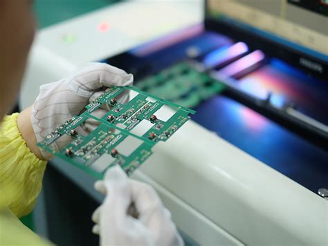
5. Automated Optical Inspection (AOI)
AOI systems use high-resolution cameras and AI to detect defects automatically.
How AOI Works:
- The PCB is scanned under multiple angles.
- Software compares images with design specifications.
- Detects solder bridges, missing components, and misalignments.
Advantages:
- High-speed inspection.
- Reduces human error.
Limitations:
- Cannot detect internal layer defects.
- High initial setup cost.
6. X-Ray Inspection (AXI)
For multilayer PCBs, X-ray inspection is essential to detect hidden shorts.
Process:
- The PCB is placed in an X-ray machine.
- The system generates cross-sectional images.
- Inspectors analyze internal traces and vias.
Advantages:
- Detects internal defects.
- Non-destructive testing.
Limitations:
- Expensive equipment.
- Requires skilled operators.
7. Flying Probe and Bed of Nails Testing
Automated test equipment (ATE) like flying probe testers and bed of nails fixtures can detect shorts efficiently.
Flying Probe Test:
- Uses movable probes to check connectivity.
- No custom fixture needed.
Bed of Nails Test:
- Uses a fixture with multiple spring-loaded pins.
- Tests multiple points simultaneously.
Advantages:
- High accuracy.
- Suitable for mass production.
Limitations:
- High setup cost for bed of nails.
- Flying probe testing is slower for large batches.
8. Current Tracing with a Power Supply
A variable power supply can help locate shorts by monitoring current draw.
Procedure:
- Set the power supply to a low voltage (e.g., 1V).
- Connect it to the PCB’s power and ground.
- Observe current flow (a short will cause high current).
- Use a thermal camera or alcohol evaporation to find hotspots.
Advantages:
- Effective for isolating shorts in power rails.
Limitations:
- Risk of damaging components if voltage is too high.
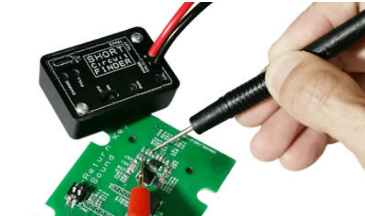
9. Advanced Techniques: Short Circuit Tracers
Specialized tools like short circuit tracers inject signals and detect interruptions.
How It Works:
- A signal generator applies a pulse.
- A receiver detects signal leakage points.
- Helps locate shorts in complex PCBs.
Advantages:
- Precise for multilayer PCBs.
- Non-destructive.
Limitations:
- Expensive equipment.
10. Conclusion
Detecting PCB short circuits requires a combination of methods depending on complexity:
- Simple PCBs: Visual inspection + multimeter.
- Multilayer PCBs: X-ray + thermal imaging.
- Mass production: AOI + automated testing.
By applying the right techniques, engineers can efficiently identify and resolve short circuits, ensuring reliable PCB performance.
Final Tips for PCB Short Prevention:
✔ Use proper soldering techniques.
✔ Inspect PCBs at multiple production stages.
✔ Implement design rule checks (DRC) to avoid trace spacing issues.
✔ Test prototypes thoroughly before full-scale production.
By following these methods, PCB manufacturers and technicians can minimize short circuit risks and enhance product reliability.