Rigid flex pcb applications
1. Medical devices:
Rigid-flex PCBs are used in medical devices such as pacemakers, defibrillators, and implantable devices due to their flexibility and compact size.
2. Aerospace and defense:
Rigid-flex PCBs are used in aerospace and defense applications such as avionics, satellites, and missiles due to their ability to withstand harsh environments and vibrations.
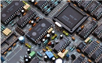
3. Consumer electronics:
Rigid-flex PCBs are used in consumer electronics such as smartphones, tablets, and wearables due to their ability to reduce the size and weight of the device.
4. Automotive:
Rigid-flex PCBs are used in automotive applications such as dashboard electronics, airbag sensors, and engine control units due to their ability to withstand high temperatures and vibrations.
5. Industrial automation:
Rigid-flex PCBs are used in industrial automation applications such as robotics, sensors, and control systems due to their ability to withstand harsh environments and vibrations.
Overall, rigid-flex PCBs offer a versatile and reliable solution for a wide range of applications where space is limited and flexibility is required.

Application examples of soft and hard board
Soft board:
1. Bulletin board:
A soft board is commonly used as a bulletin board in offices, schools, and community centers.
It is used to post notices, announcements, and other important information.
2. Art and craft:
Soft boards are also used in art and craft projects.
They can be used as a base for creating collages, displaying artwork, or creating vision boards.
3. Home décor:
Soft boards can be used as a decorative element in homes.
They can be covered with fabric or wallpaper to match the décor of the room and used to display photos, artwork, or other decorative items.
Hard board:
1. Furniture:
Hard boards are commonly used in furniture manufacturing.
They are used to make shelves, cabinets, and other furniture pieces.
2. Building construction:
Hard boards are used in building construction as a sheathing material.
They are used to cover walls, roofs, and floors.
3. Packaging:
Hard boards are used in packaging to create boxes, cartons, and other packaging materials.
They are used to protect products during transportation and storage.

To create a rigid-flex PCB prototype, you will need to follow these steps:
1. Design the PCB:
Use a PCB design software to create the layout of your rigid-flex PCB.
Make sure to include all the necessary components, traces, and vias.
2. Choose the materials:
Select the materials you want to use for the rigid and flexible portions of the PCB.
Common materials include FR-4, polyimide, and copper.
3. Fabricate the PCB:
Send your design files to a PCB manufacturer to have your prototype fabricated.
Make sure to specify that you need a rigid-flex PCB.
4. Assemble the PCB:
Once you receive the fabricated PCB, you can begin assembling it by soldering the components onto the board.
5. Test the PCB:
Test the functionality of the PCB to ensure that it is working as intended.
6. Iterate and improve:
Based on the results of your testing, make any necessary changes to the design and repeat the process until you have a final product that meets your requirements.
It is important to note that the process of creating a rigid-flex PCB prototype can be complex and may require specialized knowledge and equipment.
It is recommended to work with a reputable PCB manufacturer or supplier who has experience with rigid-flex PCBs to ensure the best results.
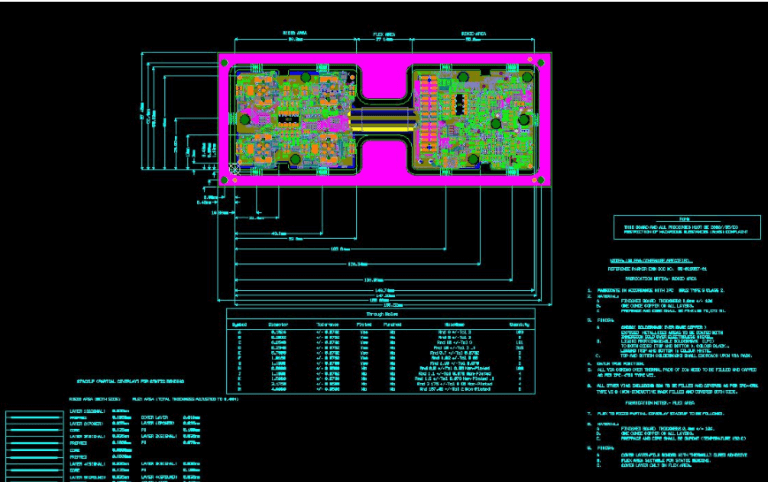
rigid-flex pcb prototype design
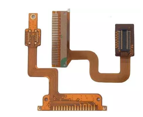
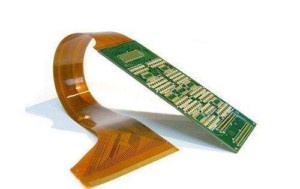
Rigid-flex PCB prototype design is a type of printed circuit board (PCB) that combines both rigid and flexible materials in a single board.
This type of design is commonly used in applications where space is limited,
and the board needs to be able to bend or flex to fit into a specific shape or form factor.

The design process for a rigid-flex PCB prototype involves several steps:
1. Determine the requirements:
The first step is to determine the requirements for the board, including the size, shape, and functionality.
2. Select the materials:
The next step is to select the appropriate materials for the rigid and flexible portions of the board.
Common materials used for the rigid portion include FR-4 and aluminum, while materials used for the flexible portion include polyimide and polyester.
3. Create the layout:
Once the materials have been selected, the next step is to create the layout for the board.
This involves placing the components and traces on the board in a way that meets the requirements and allows for the necessary flexibility.
4. Verify the design:
After the layout has been created, it is important to verify the design using simulation software or by creating a physical prototype.
5. Manufacture the prototype:
Once the design has been verified, the next step is to manufacture the prototype.
This involves using a combination of traditional PCB manufacturing techniques and specialized techniques for the flexible portion of the board.
6. Test the prototype:
Finally, the prototype should be tested to ensure that it meets the requirements and functions as intended.
Overall, designing a rigid-flex PCB prototype requires careful attention to detail and a thorough understanding of the materials and manufacturing processes involved.