Rigid Flex PCB Assembly Process
Rigid-flex PCB assembly consists of several steps to follow to complete a successful assembly. For instance, the substrate used for the assembly must be of the right material to ensure durability and strength. It also has to be resistant to heat and chemicals.
Additionally, the substrate must be flexible enough to allow easy access to circuitry areas. Combined with the substrate, flexible film and adhesives are made for cover lays, which provide all-inclusive protection and accessibility to circuit pads.
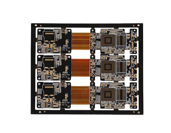
Step 1: Preparing material
Before manufacturing our rigid-flex PCB, we clean our copper-clad laminates (CCL) and cut polyimide (PI), coverlay, prepreg, stiffeners, and the chemically cleaned CCL into the appropriate sizes.
Step 2: Creating the flex section’s inner core
We will need an internal flex board to manufacture rigid-flex PCB. In addition, we must generate the inner core of the flex to manufacture the flex board.
However, if our rigid-flex design has a single flex layer on the PI, we must wrap a thin copper foil. Similarly, if there are two or more flex layers in the rigid-flex, we need to laminate a couple of external copper foils on the PI.

Step 3: Creating the flex inner core circuits
In this case, we aim to leave a particular pattern of copper traces on the foil and eliminate the rest copper composition. We first coat the copper foil with a curable photoresist in case of UV irradiation. Next, we use a nontransparent film and draw the transparent PCB connections on the copper foil.
Turning on UV light, the cured dry film covers and protects the copper traces in our PCB circuit pattern. Next, using our chemical solution, we now wash away the uncured photoresist. Finally, we dissolve the exposed copper using NaOH solution, leaving only our copper circuit traces on the inner core.
Step 4: Laminating, generating the circuits, and drilling holes on the flex Section
We laminate the PI layers depending on the number of flexible layers in the rigid-flex design. Therefore, if the number of flexible layers in the rigid-flex design exceeds two, we laminate alternating copper foil and PI layers on our flex inner core. Next, we start creating the circuits.
On the other hand, if there are two or only a single flexible layer, we proceed to circuit generating.

Generating the circuit on the external flex layers is our last step. However, in this case, we retain the rest of the copper and remove the copper traces in the PCB circuit. We first use copper to electroplate the circuit area before electroplating it with tin.
Next, having protected the circuit area with tin, we remove the photoresist and wash away the copper remaining in the non-circuit area using NaOH.
We now remove the tin and keep the electroplated copper traces on the external flex layers. Next, we drill through holes on the plate using a laser before laminating the coverlay on the flex layers. Finally, we’ve completed the flex region.
Step 5: Rigid layer lamination, circuit generation, and drilling
We laminate alternating prepreg layers and copper foil if our rigid-flex PCB has plated-through holes. Next, we generate the circuit and mechanically drill through holes on the board.
On the other hand, we use a laser to drill alternating prepreg layers and copper oil if the rigid-flex PCB has HDI requirements. Having laminated alternating flex layers, we finally generate the circuits on the boards’ rigid layers.
Step 6: Using the laser to cut off excess prepreg in off the flex region
To expose the flex section we need, we cut off the prepreg area outside the circuit using a laser.
Step 7: Finalize our PCB manufacturing process and test its functioning
On the surface of the rigid-flex PCB, we apply our surface finish, silkscreen, and solder mask before treating the panel’s edge half holes and V-cut.
Finally, we carry out the nail-in-bed and flying probe, the main tests. In addition, for components applicable in the military, medicine, aerospace, and automotive industries, we must carry out the four-terminal sensing test. We have completed the manufacturing process.
Other PCB products, you may interesting


