Simple PCB Circuits: Design, Components, and Applications
Introduction
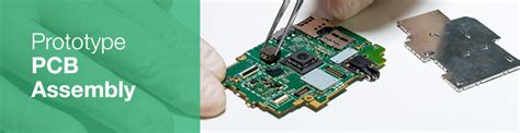
Printed Circuit Boards (PCBs) are the backbone of modern electronics, providing a reliable and efficient way to connect electronic components. A simple PCB circuit is an excellent starting point for beginners learning electronics, as it introduces fundamental concepts such as schematic design, component placement, soldering, and testing. This article explores the basics of a simple PCB circuit, including its design process, essential components, and practical applications.
1. What is a Simple PCB Circuit?
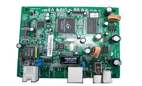
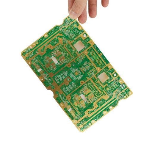
A simple PCB circuit consists of a few electronic components mounted on a non-conductive board with copper traces that form electrical connections. Unlike complex multi-layer PCBs, simple circuits typically use a single-sided or double-sided board with minimal components, making them ideal for learning and prototyping.
Key Characteristics:
- Low component count (resistors, capacitors, LEDs, transistors, etc.)
- Single or double-layer PCB design
- Basic functionality (e.g., LED blinkers, voltage regulators, sensors)
- Hand-solderable components (through-hole or basic SMD parts)
2. Essential Components in a Simple PCB Circuit
A basic PCB circuit includes several key components that work together to perform a specific function. Below are some of the most common elements:
A. Resistors
- Function: Limit current flow and divide voltages.
- Example Use: Protecting an LED from excessive current.
B. Capacitors
- Function: Store and release electrical energy, filter noise.
- Example Use: Smoothing voltage in a power supply circuit.
C. Diodes & LEDs
- Function: Allow current flow in one direction (diodes); emit light (LEDs).
- Example Use: Rectification in power circuits or indicator lights.
D. Transistors (BJT/MOSFET)
- Function: Amplify or switch electronic signals.
- Example Use: Driving motors or switching high-power loads.
E. Integrated Circuits (ICs)
- Function: Perform complex operations (e.g., timers, amplifiers).
- Example Use: 555 timer IC for generating pulse signals.
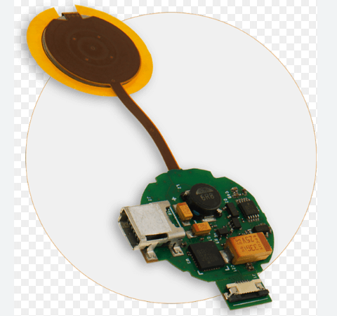
F. Connectors & Headers
- Function: Provide external connections (power, sensors, etc.).
- Example Use: USB or battery connectors.
3. Designing a Simple PCB Circuit
The design process involves several steps, from schematic creation to final fabrication.
Step 1: Schematic Design
- Draw the circuit diagram using software like KiCad, Eagle, or EasyEDA.
- Define component connections and power requirements.
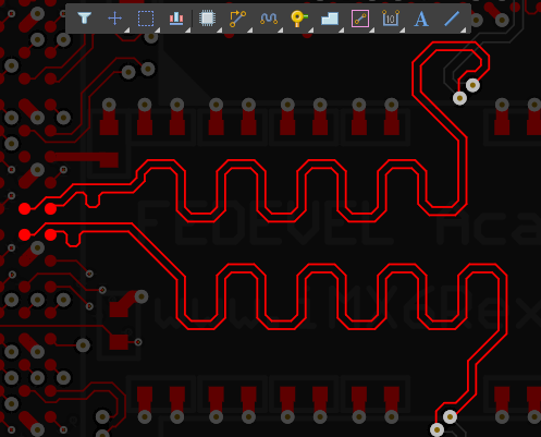
Step 2: PCB Layout
- Place components logically to minimize trace lengths.
- Route copper traces while avoiding unnecessary crossings.
- Ensure proper spacing to prevent short circuits.
Step 3: Design Rule Check (DRC)
- Verify that the PCB meets manufacturing constraints (trace width, hole sizes, etc.).
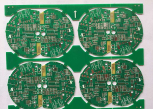
Step 4: Fabrication
- Export Gerber files and send them to a PCB manufacturer.
- Alternatively, etch a DIY PCB using the toner transfer method.
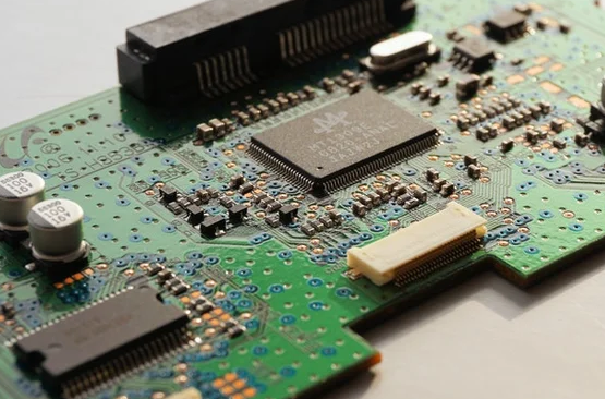
Step 5: Assembly & Testing
- Solder components onto the PCB.
- Test functionality with a multimeter or oscilloscope.
4. Example: Simple LED Blinker Circuit
A classic beginner project is an LED blinker using a 555 timer IC.
Components Needed:
- 555 Timer IC
- Resistors (1kΩ, 10kΩ)
- Capacitor (10µF)
- LED
- 9V Battery & Connector
Circuit Operation:
- The 555 IC is configured in astable mode, generating a continuous square wave.
- The resistor-capacitor (RC) network sets the blinking frequency.
- The LED turns on/off based on the output signal.
PCB Design Tips:
- Place the 555 IC centrally for easy routing.
- Keep power traces thick to reduce resistance.
- Add a decoupling capacitor near the IC for stability.
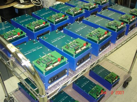
5. Applications of Simple PCB Circuits
Simple PCB circuits are widely used in:
- Educational Kits (learning electronics)
- Prototyping (testing concepts before full-scale production)
- DIY Electronics (home automation, wearable devices)
- Consumer Electronics (remote controls, chargers)
6. Advantages of Using PCBs Over Breadboards
While breadboards are useful for prototyping, PCBs offer:
✔ Better durability (no loose connections)
✔ Compact design (smaller than breadboard setups)
✔ Professional finish (suitable for final products)
✔ Improved signal integrity (reduced noise and interference)
7. Common Mistakes & Troubleshooting
A. Poor Soldering
- Issue: Cold joints or solder bridges.
- Fix: Use adequate heat and flux; inspect under a magnifier.
B. Incorrect Component Placement
- Issue: Wrong polarity or misplaced parts.
- Fix: Double-check the schematic before soldering.
C. Short Circuits
- Issue: Traces touching due to poor design.
- Fix: Run a DRC and ensure proper spacing.
D. Power Issues
- Issue: Circuit not receiving correct voltage.
- Fix: Verify connections with a multimeter.
8. Coclusion
Simple PCB circuits serve as an excellent introduction to electronics, offering hands-on experience in design, assembly, and troubleshooting. By understanding basic components, following proper design practices, and learning from common mistakes, beginners can progress to more complex projects. Whether for education, prototyping, or DIY applications, mastering simple PCB circuits is a fundamental skill for any electronics enthusiast.