The 3W Rule in PCB Routing: A Comprehensive Guide
Introduction to PCB Routing Fundamentals
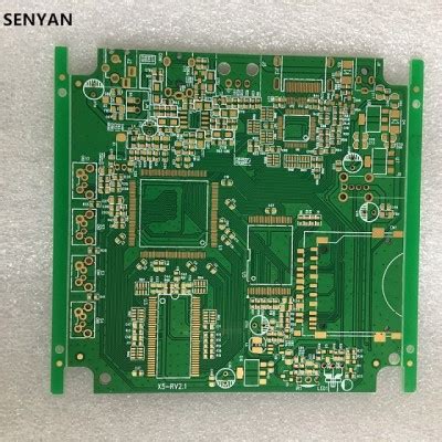
Printed Circuit Board (PCB) routing is a critical aspect of electronic design that directly impacts signal integrity, electromagnetic compatibility (EMC), and overall system performance. Among the various guidelines that govern effective PCB layout, the 3W rule stands out as a fundamental principle for minimizing crosstalk and ensuring proper signal isolation.
The 3W rule is a design guideline that specifies the minimum spacing between adjacent traces to reduce unwanted electromagnetic coupling. This principle states that the center-to-center spacing between two parallel traces should be at least three times the width of a single trace (3W) to maintain adequate isolation. While seemingly simple, proper application of this rule requires understanding its theoretical basis, practical implications, and limitations in modern high-speed designs.
Understanding the 3W Rule
Definition and Basic Concept
The 3W rule establishes that for parallel PCB traces carrying signals, the distance between their centers should be no less than three times the width of an individual trace. For example, if a trace is 10 mils (0.010 inches) wide, adjacent traces should maintain at least 30 mils center-to-center spacing.
This guideline primarily addresses the issue of crosstalk—the unwanted transfer of energy from one transmission line to another through capacitive (electric field) and inductive (magnetic field) coupling. By maintaining sufficient spacing, the 3W rule helps to:
- Reduce mutual capacitance between traces
- Minimize mutual inductance effects
- Decrease electromagnetic interference between signals
- Improve overall signal integrity
Physics Behind the 3W Principle
The effectiveness of the 3W rule stems from the nature of electromagnetic field propagation around PCB traces. The electric and magnetic fields surrounding a current-carrying conductor diminish with distance, though not linearly. Research has shown that approximately 70% of the electromagnetic field energy is contained within a distance equal to the trace width (W) from the conductor’s edge. At 2W spacing (center-to-center), about 30% of the field energy remains to potentially couple with adjacent traces. By extending this to 3W, the coupled energy drops to around 10-15%, which is often acceptable for many applications.
This relationship follows the inverse square law for field strength reduction with distance, though the exact coupling reduction depends on several factors including:
- Dielectric constant of the PCB material
- Trace thickness and geometry
- Presence of reference planes
- Signal frequency content
Application of the 3W Rule in PCB Design
When to Apply the 3W Rule
The 3W guideline is particularly important in the following scenarios:
- High-Speed Digital Signals: Fast edge rates (short rise/fall times) generate significant high-frequency content that can easily couple to adjacent traces.
- Analog Sensitive Circuits: Low-level analog signals vulnerable to noise pickup from nearby digital signals.
- Differential Pairs: While differential signals have inherent noise rejection, maintaining proper spacing to other signals prevents common-mode noise generation.
- Clock Signals: These periodic signals are particularly prone to both generating and being affected by crosstalk.
- High-Impedance Circuits: Circuits with high impedance nodes are more susceptible to capacitive coupling.
Practical Implementation Guidelines
To effectively implement the 3W rule in PCB layouts:
- Determine Critical Signals: Identify which signals require protection or are likely to interfere with others.
- Calculate Required Spacing: Based on your trace width (often determined by current-carrying capacity or impedance requirements), compute the 3W spacing.
- Prioritize Routing Layers: Apply the rule most strictly on layers without adjacent reference planes where field spreading is greater.
- Consider Edge Cases: For very sensitive signals or extremely noisy lines, consider increasing spacing beyond 3W.
- Maintain Consistency: Apply the rule uniformly throughout the design to avoid localized coupling issues.
Limitations and Considerations
Situations Where 3W May Be Insufficient
While the 3W rule provides a good baseline, certain circumstances demand greater spacing or additional measures:
- Very High-Speed Designs (>1GHz): As frequencies increase, electromagnetic fields extend further, potentially requiring 4W or 5W spacing.
- High-Voltage Applications: Where voltage differentials between traces exceed a few hundred volts, greater spacing may be needed for electrical safety.
- Extremely Sensitive Analog Circuits: Precision measurement circuits may need additional isolation techniques beyond spacing alone.
- Dense Designs: When board space is limited, alternative crosstalk reduction methods must supplement or replace the 3W approach.
Complementary Design Techniques
For situations where the 3W rule alone is inadequate or impractical, designers can employ additional strategies:
- Ground Guard Traces: Placing grounded copper between sensitive traces provides additional isolation.
- Proper Layer Stackup: Routing sensitive traces on layers adjacent to solid reference planes contains fields more effectively.
- Shielding: Copper pours or metallic shields can isolate critical sections.
- Orthogonal Routing: Routing adjacent layers perpendicular to each other minimizes overlap coupling.
- Termination Techniques: Proper termination reduces reflections that can exacerbate crosstalk.
Advanced Topics and Modern Adaptations
3W Rule in High-Density Interconnect (HDI) Designs
Modern HDI designs with trace widths and spacings below 4 mils present challenges for strict 3W adherence. In these cases:
- Microstrip vs. Stripline Considerations: Stripline configurations (traces between planes) generally require less spacing than microstrip (surface traces) for equivalent isolation.
- Differential Pair Adjustments: The 3W rule applies to spacing between pairs rather than within pairs where tighter coupling is desired.
- Via Spacing: The 3W concept extends to via placement, particularly for through-hole vias that can act as coupling antennas.
Frequency-Domain Analysis
At higher frequencies, wavelength becomes a significant factor, and the 3W rule should be evaluated in context:
- Wavelength Considerations: For traces longer than λ/10, transmission line effects dominate, and spacing requirements may change.
- Harmonic Content: Even if the fundamental frequency seems low, fast edges generate harmonics that require high-frequency spacing considerations.
- Material Effects: The dielectric constant (Dk) of PCB materials affects field propagation and thus coupling at different frequencies.
Verification and Testing
Simulation Methods
Modern EDA tools offer several ways to verify 3W rule effectiveness:
- 3D Field Solvers: Calculate exact electromagnetic field distributions between traces.
- Crosstalk Simulation: Predict coupled noise levels for given geometries.
- Eye Diagram Analysis: Assess signal integrity impacts of various spacing scenarios.
Measurement Techniques
Physical verification methods include:
- Time-Domain Reflectometry (TDR): Measures impedance variations caused by nearby traces.
- Network Analysis: Characterizes S-parameters to quantify coupling.
- Near-Field Scanning: Maps electromagnetic fields around traces experimentally.
Conclusion and Best Practices
The 3W rule remains a valuable guideline in PCB design, offering a straightforward method to control crosstalk and maintain signal integrity. However, modern electronic systems require designers to understand both the principles behind this rule and its limitations. Effective implementation involves:
- Contextual Application: Apply the rule judiciously based on signal types, frequencies, and board constraints.
- Complementary Techniques: Combine spacing with other isolation methods when needed.
- Verification: Always simulate or measure critical interfaces to confirm performance.
- Documentation: Clearly specify spacing requirements in design guidelines for consistency across projects.
As PCB technology continues advancing with higher speeds and densities, the fundamental concepts embodied in the 3W rule will remain relevant, even if specific implementations evolve. By understanding the underlying physics and applying the principle thoughtfully, designers can create robust, reliable circuits while meeting ever-increasing performance demands.
Remember that while rules of thumb like 3W provide excellent starting points, every design requires careful consideration of its unique requirements and constraints. The most successful PCB layouts balance proven guidelines with targeted analysis to achieve optimal results.