The Basic Operating Principles of PCB Relays
Introduction to PCB Relays
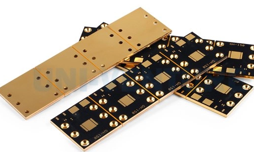
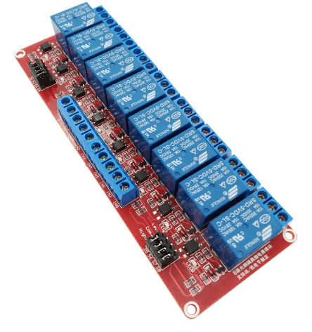
Printed Circuit Board (PCB) relays are electromechanical switching devices designed specifically for mounting on printed circuit boards. These compact components serve as crucial interfaces between low-power control circuits and higher-power load circuits in countless electronic applications. PCB relays combine the reliability of electromechanical switching with the convenience of direct PCB integration, making them indispensable in modern electronics from industrial control systems to automotive applications and household appliances.
Unlike traditional relays that require separate sockets or mounting hardware, PCB relays feature solderable pins or surface-mount terminations that allow direct attachment to circuit boards. This integration provides space savings, improved reliability by eliminating separate connections, and enables automated assembly processes. The fundamental operating principle of PCB relays mirrors that of conventional electromechanical relays, but their design optimizes them for board-level implementation.
Electromechanical Fundamentals
At their core, all electromechanical relays, including PCB-mounted varieties, operate based on the interaction between electricity and magnetism. When an electric current passes through a coil of wire, it generates a magnetic field according to Ampère’s circuital law. This electromagnetic effect forms the foundation of relay operation.
The coil in a PCB relay typically consists of many turns of fine copper wire wound around a ferromagnetic core. When energized, this coil creates a magnetic flux that magnetizes the core and surrounding magnetic circuit. The strength of this magnetic field depends on several factors:
- Number of turns in the coil (N)
- Current flowing through the coil (I)
- Magnetic permeability of the core material
- Physical dimensions of the magnetic circuit
PCB relays optimize these parameters to achieve reliable operation with minimal power consumption while maintaining compact dimensions suitable for board mounting.
Contact Mechanism Operation
The magnetic field generated by the energized coil actuates the relay’s contact mechanism through precise mechanical linkage. Most PCB relays employ one of two common armature designs:
1. Hinged Armature Design:
This traditional configuration features a pivoted armature that rotates when attracted to the electromagnet. The armature connects to movable contacts that open or close against stationary contacts. Hinged designs offer good contact pressure and are common in general-purpose PCB relays.
2. Balanced Force Armature Design:
Used in more compact relays, this design employs a flat armature suspended by springs or flexible members. When energized, the armature moves linearly toward the coil core, transferring this motion to the contacts. This design allows for lower profile relays suitable for high-density PCB mounting.
The contact mechanism must overcome several mechanical forces:
- Spring tension that maintains the unenergized state position
- Friction in moving parts
- Air resistance during rapid movement
- Contact rebound forces upon impact
PCB relay designs carefully balance these forces to ensure reliable operation while minimizing the required coil power.
Contact Arrangements and Switching
PCB relays come in various contact configurations to suit different circuit requirements:
Form A (Normally Open – NO):
Contacts remain open when the relay is de-energized and close when energized. This is the most common configuration for switching loads.
Form B (Normally Closed – NC):
Contacts remain closed when de-energized and open when energized. Used for break-before-make applications or fail-safe circuits.
Form C (Changeover or SPDT):
Combines both NO and NC contacts with a common terminal, allowing the relay to switch between two circuits. Also called “transfer” contacts.
Form D (CO or DPDT):
Double-pole double-throw configurations provide two separate sets of Form C contacts operated simultaneously by a single coil.
The contact materials in PCB relays are carefully selected based on the intended application:
- Silver alloy contacts for general purpose switching
- Gold-plated contacts for low-level signals
- Tungsten or special alloys for high-current applications
- Mercury-wetted contacts (in specialized relays) for bounce-free operation
Contact ratings specify the maximum voltage and current the relay can switch reliably. PCB relays typically range from small signal versions handling milliamps to power relays capable of switching 10-20 amps.
Coil Circuit Considerations
The coil side of a PCB relay represents the control portion of the circuit. Several important parameters govern coil operation:
Coil Voltage:
PCB relays are available with standardized coil voltages matching common control circuit levels (3V, 5V, 12V, 24V DC or AC). The actual operating voltage can typically vary ±10% from nominal.
Coil Resistance:
Determines the current draw (I = V/R) and power consumption (P = V²/R) of the relay. PCB relays optimize coil resistance to provide sufficient magnetic force while minimizing power dissipation.
Pick-up Voltage:
The minimum coil voltage required to reliably energize the relay (typically 75-80% of nominal voltage).
Drop-out Voltage:
The maximum voltage at which an energized relay will reliably release (typically 10-15% of nominal voltage).
Coil Suppression:
When de-energized, the collapsing magnetic field induces a high voltage spike across the coil that can damage control circuitry. PCB relays often incorporate suppression components:
- Free-wheeling diodes
- RC snubber networks
- Varistors
- Zener diodes
Some PCB-mounted relays include these suppression components internally, while others require external protection circuits on the PCB.
Dynamic Operation Characteristics
Understanding the dynamic behavior of PCB relays is essential for proper circuit design:
Operate Time:
The interval between coil energization and contact closure. Typically ranges from 1-15 milliseconds for PCB relays, depending on design and size.
Release Time:
The interval between coil de-energization and contact return to unoperated position. Generally slightly longer than operate time due to residual magnetism.
Contact Bounce:
Mechanical vibration of contacts during closure causes brief intermittent connections lasting typically 0.1-5 ms. This can generate electrical noise and multiple transitions that digital circuits may interpret as separate events.
Switching Frequency:
The maximum rate at which a relay can cycle while maintaining reliable operation. Limited by mechanical inertia and thermal considerations, typically a few operations per second for general purpose PCB relays.
Mechanical Life:
The number of operations the relay can perform without electrical load, typically millions for quality PCB relays.
Electrical Life:
The number of operations under specified load conditions before contact degradation affects performance. Varies greatly with load type and current.
PCB Integration Considerations
Several factors specific to printed circuit board implementation influence PCB relay design and selection:
Mounting Style:
- Through-hole (leaded) versions with standard pin spacing (5mm, 7.62mm, 10mm etc.)
- Surface-mount (SMD) versions for automated assembly
- Hybrid designs with coil connections on one side and contacts on the other
Termination Types:
- Standard straight or right-angle pins
- Gull-wing leads for SMD versions
- Press-fit terminations for high-vibration environments
PCB Layout Considerations:
- Clearance and creepage distances for high voltage applications
- Thermal management for power relays
- Trace sizing for coil and contact currents
- Isolation between control and load circuits
Environmental Factors:
- Conformal coatings may affect operation of non-sealed relays
- Vibration resistance requirements
- Operating temperature range
- Humidity and contamination protection
Applications and Selection Criteria
PCB relays find application across virtually all electronic sectors:
Industrial Control:
- PLC I/O modules
- Machine control
- Process automation
Automotive Electronics:
- Body control modules
- Power distribution
- Safety systems
Telecommunications:
- Line switching
- Test equipment
- Network infrastructure
Consumer Electronics:
- Appliances
- HVAC controls
- Power management
Medical Equipment:
- Patient monitoring
- Diagnostic devices
- Treatment systems
Key selection parameters for PCB relays include:
- Coil voltage and power requirements
- Contact configuration and rating
- Switching speed requirements
- Environmental conditions
- Expected lifetime
- Physical size constraints
- Agency approvals (UL, VDE, etc.)
- Cost considerations

Advancements and Alternatives
While traditional electromechanical PCB relays remain widely used, several technological advancements and alternatives have emerged:
Solid State Relays (SSRs):
Semiconductor-based devices offering faster switching, longer life, and silent operation, but with different characteristics regarding leakage current, voltage drop, and transient susceptibility.
Reed Relays:
Combine the coil of an electromechanical relay with reed switches, offering faster operation and smaller size for specific applications.
Latching Relays:
Use permanent magnets or mechanical mechanisms to maintain state without continuous coil power, reducing energy consumption.
High-Frequency Relays:
Specialized designs optimized for RF signal switching with controlled impedance and minimal signal degradation.
Safety Relays:
Incorporating forced-guided contacts for reliable detection of contact welding in safety-critical applications.
Conclusion
PCB relays continue to play a vital role in electronic circuit design by providing reliable, electrically isolated switching in a compact, board-mountable package. Their operation based on fundamental electromechanical principles ensures robust performance across diverse applications. Understanding the interaction between the electromagnetic coil, mechanical actuator, and contact system allows engineers to properly select and implement PCB relays in their designs. While alternative technologies exist for specific applications, the combination of electrical isolation, contact versatility, and proven reliability ensures electromechanical PCB relays will remain essential components in electronic systems for the foreseeable future.