Thermal Analysis Issues in PCB Design: Challenges and Solutions
Abstract
Printed Circuit Board (PCB) thermal management has become a critical aspect of electronic design as component densities increase and power requirements grow. This paper examines the fundamental thermal analysis problems in PCB design, including heat generation mechanisms, thermal transfer pathways, and common failure modes related to overheating. We explore various analytical methods, from basic calculations to advanced computational techniques, and discuss practical solutions for thermal mitigation. The paper also reviews industry standards and provides case studies demonstrating effective thermal management strategies in modern PCB designs.
Keywords: PCB thermal analysis, heat dissipation, thermal management, electronic cooling, finite element analysis
1. Introduction
As electronic devices continue to shrink in size while increasing in functionality and power, thermal management in Printed Circuit Boards (PCBs) has emerged as one of the most critical challenges in electronic design. Proper thermal analysis ensures device reliability, prevents premature failure, and maintains optimal performance. This paper addresses the fundamental thermal analysis problems encountered in PCB design and presents practical solutions employed in the industry.
Modern PCBs often incorporate high-power components such as processors, power converters, and RF modules that generate significant heat within confined spaces. Without proper thermal design, these boards can experience a range of problems including solder joint failure, delamination, component degradation, and complete system failure. Industry studies suggest that over 55% of electronic failures are thermally related, making thermal analysis an essential part of the PCB design process.
2. Heat Generation Mechanisms in PCBs
2.1 Resistive Heating
The primary source of heat in PCBs comes from resistive (Joule) heating in conductors and components. This occurs when current flows through materials with finite conductivity, following the fundamental relationship:
P = I²R
Where P is power dissipated as heat, I is current, and R is resistance. Trace resistance, via resistance, and component internal resistances all contribute to this heating effect.
2.2 Dielectric Losses
In high-frequency applications (>1GHz), dielectric materials in the PCB substrate can absorb electromagnetic energy and convert it to heat. The loss tangent (tanδ) of the material determines the magnitude of these losses.
2.3 Component Power Dissipation
Active components (ICs, transistors, regulators) and some passive components (power resistors) convert electrical energy to heat as part of their normal operation. Modern processors can dissipate over 100W in small packages.
3. Thermal Transfer Pathways
Heat generated in a PCB follows three fundamental transfer mechanisms:
3.1 Conduction
Heat travels through solid materials from hotter to cooler regions. In PCBs, this occurs through:
- Copper traces and planes
- Vias and thermal pads
- Component leads and packages
- The substrate material itself
The effectiveness of conductive cooling depends on thermal conductivity (k) of materials, with copper (385 W/mK) being far superior to FR-4 (0.3 W/mK).
3.2 Convection
Air or liquid moving over heated surfaces carries heat away. Natural convection relies on buoyancy-driven air currents, while forced convection uses fans or pumps. Convection effectiveness depends on:
- Surface area
- Airflow velocity
- Temperature differential
- Surface properties (emissivity)
3.3 Radiation
All objects emit infrared radiation proportional to their temperature (Stefan-Boltzmann law). While generally minor in PCBs at moderate temperatures, radiation becomes significant in high-temperature or vacuum applications.
4. Common Thermal Analysis Problems
4.1 Hot Spots
Localized areas of excessive temperature typically caused by:
- High-power components with insufficient cooling
- Poor thermal via placement
- Inadequate copper distribution
- Restricted airflow
4.2 Thermal Stresses
Different coefficients of thermal expansion (CTE) between materials create mechanical stresses during temperature cycles, leading to:
- Solder joint cracking
- Pad lifting
- Delamination
- Warping
4.3 Thermal Crosstalk
Heat from one component affecting the performance of nearby components through:
- Temperature-sensitive parameter drift
- Increased leakage currents
- Changes in timing characteristics
4.4 Thermal Runaway
Positive feedback situations where increased temperature causes higher power dissipation, further increasing temperature. Common in:
- Bipolar junction transistors
- Power semiconductors
- Battery charging circuits
5. Thermal Analysis Methods
5.1 Analytical Calculations
Basic thermal estimates can be made using simplified models:
- Fourier’s law for conduction
- Newton’s law of cooling for convection
- Thermal resistance networks (analogous to electrical circuits)
5.2 Computational Fluid Dynamics (CFD)
Advanced numerical methods solve the Navier-Stokes equations to model:
- Airflow patterns
- Temperature distributions
- Heat transfer coefficients
5.3 Finite Element Analysis (FEA)
Breaks the PCB into small elements to solve heat transfer equations numerically. Provides:
- Detailed temperature maps
- Stress/strain analysis
- Transient thermal behavior
5.4 Experimental Methods
Physical measurements using:
- Thermocouples
- Infrared cameras
- Thermal test dies
- Liquid crystal thermography
6. Thermal Mitigation Techniques
6.1 PCB Layout Solutions
- Strategic placement of thermal vias under hot components
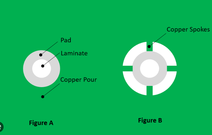
- Copper pours and thermal relief patterns
- Proper power plane design
- Component spacing considerations
6.2 Material Selection
- High thermal conductivity substrates (metal core, ceramic)
- Thermal interface materials
- High-temperature laminates
6.3 External Cooling
- Heat sinks and cold plates
- Fans and blowers
- Liquid cooling systems
- Phase change materials
6.4 Design Practices
- Derating components for thermal effects
- Implementing thermal shutdown circuits
- Considering thermal expansion matching
- Providing adequate test points for thermal validation
7. Industry Standards and Guidelines
Several standards address PCB thermal requirements:
- IPC-2152: Standard for determining current-carrying capacity
- JEDEC JESD51: Thermal test standards
- MIL-STD-810: Environmental engineering considerations
- IEC 60068: Environmental testing procedures
8. Case Studies
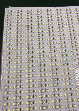
8.1 High-Power LED Array
A 100W LED module experienced premature failure due to inadequate thermal paths. Implementation of a metal-core PCB with optimized via patterns reduced junction temperatures by 35°C.
8.2 RF Power Amplifier
A 5G base station amplifier showed performance degradation at high ambient temperatures. Adding thermal vias and selecting a low-loss dielectric material improved thermal stability.
8.3 Automotive Control Unit
Vibration-induced failures were traced to CTE mismatch. Switching to a high-Tg material with matched CTE to components eliminated the issue.
9. Future Trends
Emerging technologies in PCB thermal management include:
- Embedded two-phase cooling systems
- Graphene-enhanced thermal materials
- 3D-printed heat exchangers
- AI-optimized thermal layouts
- Thermoelectric cooling integration
10. Conclusion
Effective thermal analysis is essential for reliable PCB design in today’s high-density, high-power electronic systems. By understanding heat generation mechanisms, transfer pathways, and potential failure modes, designers can implement appropriate mitigation strategies. A combination of analytical, computational, and experimental methods provides the most robust approach to thermal management. As electronic systems continue to push power and density limits, innovative thermal solutions will remain at the forefront of PCB design challenges.