Through Hole PCB Assembly Techniques for Robust Circuits
Key Takeaways
Effective PCB assembly relies on precision in through-hole technology (THT) to ensure circuit durability, particularly in demanding environments like industrial machinery and aerospace systems. Key considerations include proper component insertion, optimized soldering techniques, and rigorous inspection protocols. Unlike surface-mount technology (SMT), through-hole components provide superior mechanical strength, making them ideal for high-vibration applications.
| Aspect | Through-Hole PCBA | SMT PCBA |
|---|---|---|
| Mechanical Bond | High-strength leads | Solder paste adhesion |
| Thermal Resistance | Excellent heat dissipation | Limited by pad size |
| Repairability | Easier component replacement | Complex rework required |
For durable electronics, operators must prioritize axial/radial lead alignment during insertion and employ wave soldering to achieve uniform joints. Post-assembly, automated optical inspection (AOI) and functional testing validate signal integrity and connection reliability. While SMT dominates miniaturized designs, through-hole PCBA remains critical for mission-critical systems where failure is not an option. Transitioning to advanced methods requires balancing cost, scalability, and application-specific performance needs.
Mastering Through Hole PCB Assembly
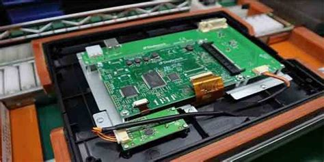
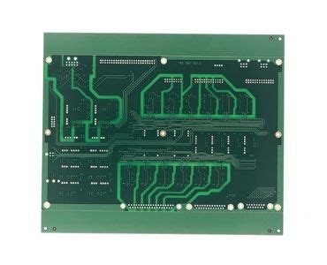
PCB assembly using through-hole technology remains a cornerstone for building robust circuits, particularly in applications demanding mechanical stability and high reliability. Unlike surface-mount technology (SMT), through-hole components feature leads inserted into pre-drilled holes on the board, creating stronger physical bonds. This method is especially critical for high-voltage or high-stress environments, such as industrial machinery or aerospace systems, where vibration resistance is non-negotiable.
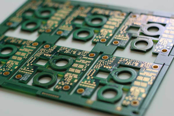
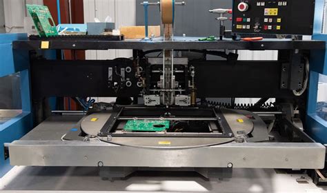
A key step in PCBA (printed circuit board assembly) involves precise component insertion. Axial and radial components—such as capacitors, connectors, and transformers—require careful alignment to avoid bent leads or misplacement. Automated insertion machines excel in high-volume production, but manual adjustments are often necessary for prototypes or specialized parts.
Tip: Always verify hole-to-lead ratios during design. A 0.1mm tolerance gap ensures smooth insertion without compromising solder joint integrity.
Soldering techniques further define the durability of through-hole assemblies. Wave soldering remains the gold standard, uniformly coating leads and pads with solder. For mixed-technology boards (combining through-hole and SMT), selective soldering minimizes thermal stress on sensitive components. Post-solder inspection, including automated optical inspection (AOI) and cross-sectional analysis, identifies voids or cracks that could compromise longevity.
By prioritizing component selection, process control, and rigorous testing, engineers leverage through-hole PCB assembly to meet stringent requirements in sectors like defense and automotive manufacturing. While SMT dominates miniaturized designs, through-hole’s mechanical advantages ensure its relevance in mission-critical applications.
Durable PCB Component Insertion Guide
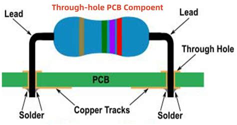
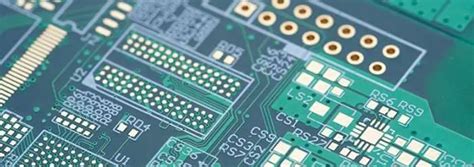
Proper component insertion forms the foundation of reliable PCB assembly processes, particularly in through hole PCBA manufacturing. To ensure durability, components must align precisely with designated holes while maintaining optimal lead protrusion—typically 1.5–2.5 mm—to facilitate effective soldering. Axial and radial leaded parts require distinct handling: axial components (e.g., resistors) demand uniform bending to avoid stress points, while radial parts (e.g., capacitors) need vertical alignment to prevent tilting during wave soldering.
For high-density boards, automated insertion machines enhance consistency, but manual correction remains critical for verifying polarity markers and footprint compatibility. Industrial-grade applications often employ dual-stage processes: pre-forming leads before placement reduces mechanical strain, while controlled insertion force (5–10 N) prevents pad delamination. Aerospace-grade PCBA mandates additional scrutiny, such as using mil-spec connectors and epoxy-sealed headers to withstand vibration and thermal cycling.
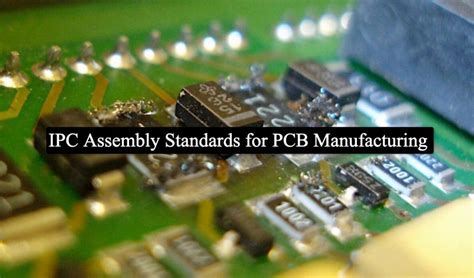
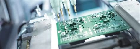
Transitioning to inspection, post-insertion checks via automated optical inspection (AOI) systems detect misalignments or bent leads before soldering. This proactive approach minimizes rework and ensures compliance with IPC-A-610 standards for through hole PCB assembly, setting the stage for robust circuit performance in demanding environments.
Soldering Techniques for Robust Circuits
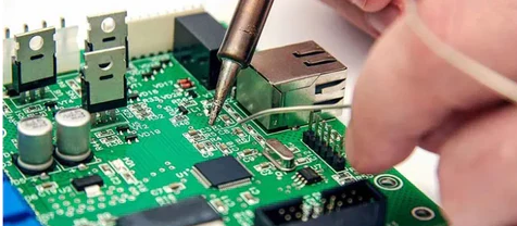
Effective soldering is critical to ensuring the long-term reliability of through-hole PCB assembly processes. Proper technique begins with selecting the right solder alloy—typically a lead-free tin-silver-copper blend for industrial or aerospace PCBA applications. Thermal management is essential: excessive heat can damage components, while insufficient heat risks cold joints. For manual soldering, a chisel-shaped tip (1.5-2.5mm) ensures optimal contact with component leads and pads. Apply solder at the junction of the lead and pad, allowing it to flow smoothly to form a concave fillet—a visual indicator of a strong bond.
In automated PCB assembly, wave soldering remains a preferred method for high-volume through-hole projects. The board passes over a molten solder wave, creating uniform connections. To prevent defects like bridging or voids, maintain a conveyor speed of 1-1.5 meters per minute and a solder pot temperature between 250°C and 265°C. For mixed-technology boards (through-hole and SMT), selective soldering systems offer precision without compromising adjacent components.
Post-soldering, inspect joints under magnification for glistening surfaces and full coverage. X-ray analysis may be necessary for aerospace-grade PCBA to detect hidden flaws. Pair these techniques with rigorous thermal cycling tests to validate durability under extreme conditions.
Reliable PCB Inspection Best Practices
Ensuring the integrity of PCB assembly requires rigorous inspection protocols, particularly for through-hole PCBA designed for demanding environments. Visual inspection remains a foundational step, where technicians verify component alignment, solder joint quality, and the absence of bridging or cold joints. For high-reliability applications, such as aerospace systems, automated optical inspection (AOI) systems are indispensable. These systems detect microscopic flaws—like insufficient solder fill or pin-hole voids—that human eyes might miss.
Complementing AOI, X-ray inspection is critical for examining hidden connections, such as plated through-holes, to ensure proper metallization and adhesion. In industrial-grade PCBA, in-circuit testing (ICT) validates electrical continuity, isolating faults like open circuits or shorted traces. For mission-critical boards, functional testing under simulated operating conditions (e.g., thermal cycling) confirms performance stability.
Documentation and traceability are equally vital. Each inspection phase should generate detailed records, including solder profile data and defect logs, to support root-cause analysis. By integrating these practices into PCB assembly workflows, manufacturers minimize field failures and align with stringent standards like IPC-A-610. This systematic approach not only safeguards circuit reliability but also prepares assemblies for subsequent comparisons with surface-mount technologies in terms of long-term durability.
Through Hole vs SMT Reliability Comparison
When evaluating PCB assembly methods, reliability hinges on application-specific demands. Through-hole technology excels in environments requiring mechanical stability and high thermal tolerance, as component leads physically anchor through the board, reducing failure risks from vibration or thermal cycling. This makes it ideal for industrial-grade PCBA systems, such as heavy machinery controls or power supply units, where long-term durability is non-negotiable. In contrast, surface-mount technology (SMT) prioritizes miniaturization and high-speed production, achieving superior signal integrity in compact devices. However, SMT joints may exhibit lower resistance to mechanical stress due to their smaller solder footprints, potentially compromising reliability in extreme conditions.
Aerospace PCB assembly often leverages through-hole components for critical subsystems—like avionics or engine controls—where failure could have catastrophic consequences. While SMT dominates consumer electronics, its reliance on reflow soldering introduces risks of void formation or component misalignment under rapid temperature shifts. For mission-critical applications, the choice between through-hole and SMT ultimately balances space constraints against operational stressors. Hybrid approaches, combining both technologies in PCBA designs, are increasingly common, allowing engineers to optimize reliability without sacrificing performance.
Industrial-Grade PCB Assembly Methods
Industrial environments demand PCB assembly processes that prioritize durability and long-term reliability. Unlike consumer-grade electronics, industrial applications expose circuits to extreme temperatures, vibration, and mechanical stress. To meet these challenges, PCBA workflows incorporate military-grade components and precision insertion techniques, ensuring components withstand harsh operating conditions. For instance, axial and radial leads are often manually secured using reinforced clinching before soldering, minimizing movement during thermal cycling.
Wave soldering remains a cornerstone of industrial PCB assembly, as it creates robust connections for through-hole components. However, process parameters—such as solder temperature, flux viscosity, and conveyor speed—are tightly controlled to prevent voids or cold joints. Post-soldering, automated optical inspection (AOI) systems scan for defects like insufficient fillets or misaligned pins, while thermal shock testing validates resilience under rapid temperature fluctuations.
Transitioning from commercial to industrial-grade PCBA requires balancing cost and performance. While surface-mount technology (SMT) offers space efficiency, through-hole assembly provides superior mechanical bonding for high-stress applications. This makes it indispensable in industrial control systems, where vibration resistance and repairability are critical. By integrating rigorous testing protocols and material selection criteria, manufacturers ensure that industrial through-hole assemblies deliver decades of fault-free operation.
Aerospace Applications for Through Hole PCBs
In aerospace engineering, where extreme temperatures, vibrations, and radiation exposure are commonplace, through hole PCB assembly remains a cornerstone for building mission-critical systems. Unlike surface-mount technology (SMT), through hole components create stronger mechanical bonds, ensuring connections withstand high-G forces during launch or turbulent flight conditions. This reliability is vital for avionics, navigation systems, and onboard communication hardware, where failure could compromise safety.
Aerospace PCBA designs often prioritize redundancy and durability, leveraging through hole mounting for high-power components like connectors and power modules. For instance, flight control systems rely on ruggedized boards assembled with dual-row headers or pin grid arrays, which resist loosening under sustained stress. Additionally, the extended thermal cycling tolerance of through hole joints—achieved via wave soldering or manual soldering—prevents cracks in solder joints during rapid temperature shifts at high altitudes.
To meet stringent industry standards like MIL-PRF-31032, aerospace PCB assembly processes incorporate rigorous inspection protocols, including automated optical inspection (AOI) and cross-sectional analysis. These steps validate solder fillet integrity and component alignment, ensuring boards perform flawlessly in environments where maintenance is impractical. As aerospace technology advances, the fusion of through hole reliability with modern PCBA innovations continues to support next-generation satellites, drones, and crewed spacecraft.
Conclusion
While modern PCB assembly trends increasingly favor surface-mount technology (SMT), through-hole PCBA remains indispensable for applications demanding unmatched mechanical stability and longevity. The inherent strength of through-hole components—anchored securely by lead wires—ensures resilience in high-stress environments, making them ideal for industrial machinery and aerospace systems. By adhering to precise component insertion protocols, optimizing wave soldering parameters, and implementing rigorous automated optical inspection (AOI), manufacturers can achieve defect-free assemblies that withstand decades of operation.
The choice between through-hole and SMT ultimately hinges on balancing reliability requirements with design constraints. For mission-critical electronics, the added durability of through-hole connections often justifies the marginally higher production complexity. As innovations in PCBA workflows continue to emerge, integrating hybrid approaches—combining through-hole robustness with SMT density—will likely define next-generation solutions for sectors where failure is not an option.
Frequently Asked Questions
What distinguishes through-hole PCB assembly from surface-mount technology (SMT)?
Through-hole PCBA involves inserting component leads into pre-drilled holes on the board, which are then soldered for mechanical stability. This method excels in high-stress environments, unlike SMT, where components sit directly on the surface.
How does PCB assembly ensure durability in industrial applications?
Robust through-hole PCB assembly relies on precise component insertion, wave soldering for uniform joints, and rigorous inspection. These steps prevent failures caused by vibration or thermal cycling, making it ideal for machinery and aerospace systems.
What are common challenges in through-hole PCBA?
Misaligned components, insufficient solder fillets, and thermal damage during soldering can compromise reliability. Automated insertion tools and temperature-controlled soldering irons mitigate these risks while maintaining consistency.
Why is inspection critical in PCB assembly processes?
Post-soldering inspections, including visual checks and automated optical inspection (AOI), identify defects like cold joints or lifted leads. For aerospace-grade boards, X-ray testing may verify internal connections, ensuring compliance with stringent safety standards.
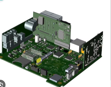
Can through-hole and SMT coexist in a single PCBA design?
Yes. Hybrid designs often use through-hole for connectors or heavy components, combined with SMT for compact ICs. This approach balances durability with space efficiency, particularly in complex industrial electronics.
Explore Custom Through-Hole PCB Solutions
For tailored PCB assembly services optimized for durability, please click here to consult our engineering team.