Understanding PCB Board Fuses: Types, Functions, and Selection Criteria
Introduction
Printed Circuit Boards (PCBs) are the backbone of modern electronics, providing a platform for interconnecting various components. One critical component often integrated into PCBs is the fuse, which plays a vital role in circuit protection. A PCB fuse is designed to prevent excessive current from damaging sensitive electronic components by breaking the circuit when an overcurrent condition occurs.
This article explores the different types of PCB fuses, their working principles, selection criteria, and applications in modern electronics.
1. What is a PCB Fuse?
A PCB fuse is a safety device installed on a printed circuit board to protect electronic circuits from overcurrent conditions. When the current exceeds a predetermined threshold, the fuse “blows” (melts or breaks), interrupting the circuit and preventing damage to other components.
Key Characteristics of PCB Fuses:
- Current Rating: The maximum current the fuse can handle without blowing.
- Voltage Rating: The maximum voltage the fuse can withstand.
- Breaking Capacity: The maximum fault current the fuse can safely interrupt.
- Response Time: How quickly the fuse reacts to overcurrent (fast-acting vs. slow-blow).
2. Types of PCB Fuses
PCB fuses come in various forms, each suited for different applications. The most common types include:
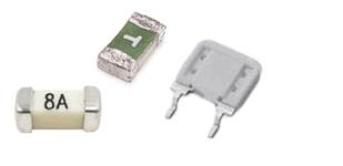
2.1. Surface-Mount Device (SMD) Fuses
- Designed for automated PCB assembly.
- Compact size, suitable for high-density circuits.
- Common packages: 0402, 0603, 1206.
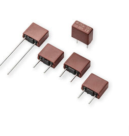
2.2. Through-Hole Fuses
- Mounted via holes in the PCB.
- More robust than SMD fuses but require manual placement.
- Used in high-power applications.
2.3. Resettable Fuses (PTC Fuses)
- Polymeric Positive Temperature Coefficient (PTC) fuses automatically reset after cooling down.
- Ideal for applications where manual fuse replacement is impractical.
- Used in USB ports, battery packs, and power supplies.
2.4. Cartridge Fuses
- Larger fuses used in high-power PCB applications.
- Often found in power supply units and industrial equipment.
2.5. Blade Fuses
- Commonly used in automotive PCBs.
- Easy to replace and available in standard sizes (e.g., ATO, mini, micro).
3. How PCB Fuses Work
The primary function of a PCB fuse is to protect against overcurrent, which can result from:
- Short circuits (sudden high current flow).
- Overloads (sustained excessive current).
- Inrush current (temporary high current at startup).
Operation Principle:
- Normal Operation: Current flows through the fuse element without heating it beyond its rated capacity.
- Overcurrent Condition: Excessive current generates heat, melting the fuse element.
- Circuit Interruption: The melted fuse breaks the circuit, stopping current flow.
Fast-Acting vs. Slow-Blow Fuses:
- Fast-Acting Fuses: React quickly to overcurrent, ideal for sensitive components.
- Slow-Blow (Time-Delay) Fuses: Tolerate temporary surges (e.g., motor startups) before blowing.
4. Selecting the Right PCB Fuse
Choosing the correct fuse for a PCB involves several considerations:
4.1. Current Rating
- Should be slightly higher than the normal operating current (typically 125-150% of max expected current).
4.2. Voltage Rating
- Must exceed the circuit’s maximum voltage to prevent arcing.
4.3. Breaking Capacity
- Must handle the highest possible fault current without failing catastrophically.
4.4. Operating Temperature
- Fuses derate at high temperatures; select one rated for the PCB’s environment.
4.5. Physical Size and Mounting Style
- SMD fuses for compact designs, through-hole for high-power circuits.
4.6. Regulatory Compliance
- Ensure fuses meet safety standards (UL, IEC, CE).
5. Applications of PCB Fuses
PCB fuses are used in various industries:
5.1. Consumer Electronics
- Smartphones, laptops, and TVs use SMD fuses for overcurrent protection.
5.2. Automotive Electronics
- Blade and PTC fuses protect vehicle ECUs, infotainment systems, and lighting.
5.3. Industrial Control Systems
- High-breaking-capacity fuses safeguard PLCs and motor controllers.
5.4. Power Supplies
- AC/DC converters and battery management systems rely on fuses for safety.
5.5. Medical Devices
- Precision fuses ensure reliable operation of diagnostic equipment.

6. Common PCB Fuse Failures and Troubleshooting
6.1. Why Do PCB Fuses Blow?
- Short circuits (e.g., solder bridges, component failure).
- Overloads (exceeding rated current for prolonged periods).
- Aging (fuse degradation over time).
6.2. How to Diagnose a Blown Fuse?
- Visual Inspection: Check for a broken filament or discoloration.
- Multimeter Test: Measure continuity; an open circuit indicates a blown fuse.
6.3. Replacing a PCB Fuse
- Always replace with the same type and rating.
- Investigate the root cause of failure to prevent recurrence.
7. Future Trends in PCB Fuse Technology
- Smart Fuses: IoT-enabled fuses with real-time monitoring.
- Nano Fuses: Ultra-miniaturized fuses for microelectronics.
- Self-Healing Materials: Research into fuses that repair themselves.
Conclusion
PCB fuses are essential for protecting electronic circuits from overcurrent damage. Understanding their types, working principles, and selection criteria ensures optimal performance and safety in electronic designs. As technology advances, smarter and more efficient fuse solutions will continue to evolve, enhancing circuit protection in next-generation electronics.
By carefully selecting and implementing the right PCB fuse, engineers can improve reliability, reduce downtime, and extend the lifespan of electronic devices.


