What are the advantages of multi-layer flexible PCBs? Sharing of flexible PCB design skills
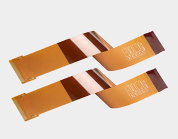
Flexible PCBs have many applications in reality, such as in mobile phones. In order to enhance everyone’s understanding of flexible PCBs, this article will introduce the advantages of flexible PCB circuits and some tips for designing flexible PCBs. If you are interested in flexible PCBs, you may wish to continue reading with the editor.
1.Advantages of multi-layer flexible circuits
Reduce assembly errors: Multi-layer flexible circuits help eliminate human errors by avoiding the use of hand-built harnesses due to design accuracy and production automation. In addition, multi-layer flexible circuits can only be routed to the points required by the planned design.
Reduce assembly costs and time: Multi-layer flexible circuits do not require much physical labor during the assembly process, thereby reducing production errors. Multi-layer flexible circuits have the inherent ability to integrate assembly, function and form. They reduce the high costs of winding, welding and wiring.
Design freedom: The form of design freedom is not limited to two dimensions, such as the case of rigid PCBs. Their flexibility can operate in the harshest environments and provide almost endless application options.
Flexibility during installation: As the name suggests, flexibility is inherent, which introduces three-dimensional design and applications. You can manipulate the flex circuit throughout the installation process without losing electronic functionality.
High-density applications: Multilayer flex circuits can accommodate high-density components. This, of course, leaves more room for other possible functions.
Improved airflow: Their streamlined design provides better airflow, which translates into lower operating temperatures and longer product lifecycles.
Better heat dissipation: With their compact design and increased surface area to volume ratio, they can provide better heat dissipation.
Improved system reliability: Multilayer flex circuits have fewer interconnects, which reduces failures and improves reliability.
Durable and reliable: Multilayer flex circuits are durable and can be flexed up to 500 million times before failure. In addition, they can withstand extreme thermal conditions.
Less complex circuit geometry: Multilayer flex circuit technology utilizes the direct placement of surface mount components onto the circuit. This allows for a simpler design.
Reduced weight and reduced package size: As you know, multiple systems that use rigid boards weigh more and require more space. However, multilayer flex circuits have been simplified and use thin dielectric substrates, eliminating the need for bulky rigid PCBs. Moreover, their flexibility and elasticity translate into smaller package sizes.
Multilayer flex circuits will continue to remain competitive and in demand as the trend toward increasing miniaturization continues. In addition, their lightweight, higher reliability, and performance in extreme environments allow them to adapt now and in the future.

2.Tips for Designing Flexible PCBs
(1)Understand How Flexible Circuits Work
Understanding the types of flexible circuits and their functions and applications will provide guidance for designing with them. Knowing what doesn’t work may be equally important. If possible, contact a reputable flexible circuit manufacturer for guidance on material properties and limitations.
(2)Build a Flexible Circuit Model
The best way to determine the feasibility of a design is to create a physical flexible circuit model. This involves first determining the system points to be electrically connected via the flexible circuit and termination methods such as mating connectors, pins, or ZIFs. Next, determine an approximate circuit “footprint” that will provide conductor routing for each terminal location. Review schematic or netlist details and special electrical requirements such as plane layers to determine the approximate number of layers. Examine sample circuits with similar numbers of layers to understand whether the proposed design will provide sufficient flexibility. If no sample circuits are available, you can get free samples from the flex circuit manufacturer.
Then review the mechanical requirements to ensure that the bend radius falls within acceptable values for circuit thickness and number of layers. Refer to IPC-2223 for guidelines on acceptable bend radius. Construct a “paper doll” outline of the flex circuit with thick paper and check it for fit. Modify as needed. Continue to build paper prototypes and modify until it fits. Finally, use 0.010-in. (0.25-mm) polyester film to rebuild the prototype to make a representative model. Mount it in the prototype housing and adjust the dimensions as needed.
(3)Get a Mechanical Sample
Before investing significant time and money to create a functional flexible circuit prototype, test mechanical samples to ensure the flexible circuit has the correct form and fit. Form refers to the physical size, shape, and quality of the part, while fit refers to its environmental interface. Mechanical samples help avoid mounting issues or potential mechanical problems that could cause failure.
(4)Minimize Circuit Cost
The main cost drivers for flex circuits are overall circuit size, number of layers, and feature size. Line width and spacing, pad size, and keyhole size cost more. Follow recommended tolerances whenever possible, and design no-bond areas only where absolutely necessary. If there are no SMT components, or they are only on one side, consider using stiffened flexes instead of rigid flexes. Stiffeners can be much cheaper than rigid-flex circuits. And use standard materials whenever possible.
(5)Don’t ignore minimum bend radius
Some problems occur when a circuit is bent too sharply. Compression on the inner radius can cause wrinkles in the cover. Stretching on the outer bend can tear the cover material and break the conductor. Start the mechanical design by establishing the bend radius. If the radius is at least ten times the material thickness, there is a good chance that the circuit will work reliably. To improve reliability, reduce the overall thickness of the bend area so it can withstand the bend.


