Why Sometimes a Resistor is Placed in Series with PCB Traces
Introduction
In printed circuit board (PCB) design, engineers occasionally place small resistors in series with signal traces, a practice that might seem counterintuitive at first glance. These resistors, typically ranging from 0 ohms to a few hundred ohms, serve multiple important functions in modern electronic circuits. This article explores the various reasons behind this common but often misunderstood design technique, examining its applications in signal integrity management, electromagnetic interference reduction, circuit protection, and more.
1. Impedance Matching and Signal Integrity
One of the primary reasons for placing series resistors in PCB traces is to achieve proper impedance matching, particularly in high-speed digital circuits.
1.1 Transmission Line Theory
At high frequencies (typically above 50-100 MHz depending on trace length), PCB traces behave as transmission lines rather than simple conductors. When the trace length approaches a significant fraction of the signal’s wavelength (generally 1/10 or more), impedance mismatches can cause signal reflections that degrade signal integrity.
1.2 Source-Series Termination
A series resistor placed close to the driver (source) can help match the source impedance to the characteristic impedance of the transmission line. This technique, called source-series termination, absorbs reflections by making the source impedance (driver output impedance plus series resistor) equal to the trace impedance. Common values range from 22Ω to 100Ω depending on the driver’s output impedance and the PCB trace characteristics.
1.3 Reducing Ringing and Overshoot
High-speed signals often exhibit ringing (oscillations) and overshoot at signal transitions due to parasitic inductance and capacitance. A properly calculated series resistor can critically damp these oscillations by increasing the circuit’s damping factor, resulting in cleaner signal transitions.
2. Controlling Rise Times and Edge Rates
Modern high-speed digital ICs feature extremely fast output drivers with rise times in the sub-nanosecond range. While fast switching is desirable for timing margins, excessively sharp edges can cause several problems:
2.1 EMI Reduction
Faster edge rates contain more high-frequency spectral components, increasing electromagnetic interference (EMI). A series resistor slows down the edge rate by forming an RC low-pass filter with the trace capacitance and load capacitance, reducing high-frequency emissions.
2.2 Crosstalk Mitigation
Sharp signal edges can couple more strongly into adjacent traces through capacitive and inductive crosstalk. By controlling the edge rate with series resistors, designers can reduce crosstalk in dense PCB layouts.
2.3 Power System Noise
Rapid current changes (di/dt) caused by fast switching can induce voltage fluctuations in power distribution networks. Slower edges reduce these current spikes, improving power integrity.
3. Current Limiting and Protection
Series resistors serve important protective functions in many circuits:
3.1 Driver Protection
In line driver applications (RS-485, CAN, etc.), series resistors limit short-circuit currents that could damage output drivers during faults or wiring errors.
3.2 Input Protection
For sensitive inputs, small series resistors (10-100Ω) work with input protection diodes to limit surge currents from electrostatic discharge (ESD) or other transient events.
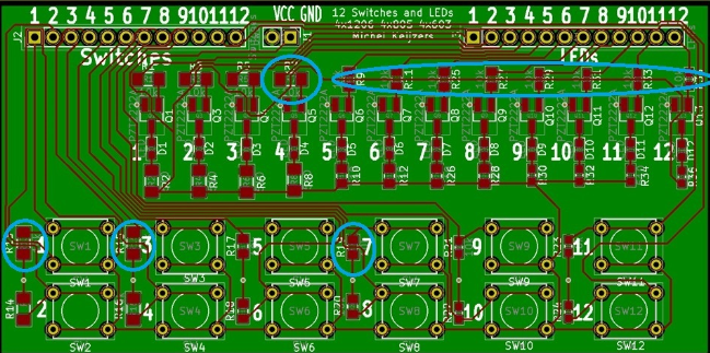
3.3 LED Current Limiting
While not strictly a PCB trace application, series resistors with LED indicator circuits perform the vital function of limiting current to safe levels.
4. Debugging and Testing Flexibility
Series resistors provide practical benefits during development and production:
4.1 Probing Points
Resistors create convenient points for attaching oscilloscope probes without disturbing the circuit operation significantly.
4.2 Circuit Isolation
During debugging, a series resistor can be removed or replaced with a higher value to isolate sections of a circuit for troubleshooting.
4.3 Configuration Options
0-ohm resistors (or “jumpers”) allow for board configuration changes without PCB redesign. These can be replaced with actual resistors if needed in future revisions.
5. Specialized Applications
Certain circuit types routinely employ series resistors for specific purposes:
5.1 Analog Signal Conditioning
In analog circuits, series resistors may be used with capacitors to form low-pass, high-pass, or filter networks directly on the PCB traces.
5.2 RF Circuits
Radio frequency designs use carefully calculated series resistors for impedance matching networks and attenuators.
5.3 Termination Networks
Some bus architectures require distributed termination where series resistors form part of more complex termination schemes.
6. Practical Implementation Considerations
When implementing series resistors in PCB designs, several factors must be considered:
6.1 Resistor Selection
Surface-mount chip resistors are typically used due to their small parasitic inductance. Values must be carefully calculated based on the specific application requirements.
6.2 Placement
For high-speed signals, series resistors should be placed close to the driver to be effective. The resistor package size (0402, 0603, etc.) affects parasitic properties.
6.3 Power Rating
While most signal applications require only 1/10W or 1/16W resistors, power applications may need higher wattage components.
6.4 Alternative Solutions
In some cases, ferrite beads may be used instead of resistors when DC continuity must be maintained while filtering high frequencies.
7. Common Pitfalls and Misconceptions
Several misunderstandings surround the use of series resistors:
7.1 “One Size Fits All” Approach
Different signals and circuits require different resistor values—using the same value everywhere often leads to suboptimal performance.
7.2 Neglecting Parasitics
The resistor’s own parasitic inductance and capacitance can affect performance at very high frequencies.
7.3 Overuse
Unnecessary series resistors can degrade signal quality and waste board space and cost.
Conclusion
The practice of placing small resistors in series with PCB traces serves multiple important functions in modern electronics design. From managing signal integrity in high-speed digital systems to providing circuit protection and debugging flexibility, these components play a role far more significant than their small size might suggest. Understanding when and how to implement series resistors effectively is an essential skill for PCB designers working with anything from simple analog circuits to cutting-edge high-speed digital systems. As signal speeds continue to increase and electronic systems grow more complex, proper use of series termination and current-limiting resistors will remain a vital tool in the designer’s toolkit.
By carefully considering the principles discussed in this article—impedance matching, edge rate control, protection, and debugging needs—engineers can make informed decisions about when and how to incorporate series resistors into their PCB designs for optimal performance and reliability.