Flexible and Flex-Foil Printed Circuit Boards: Revolutionizing Modern Electronics
Introduction
The electronics industry has undergone a significant transformation with the advent of Flexible Printed Circuit Boards (Flex PCBs) and Flex-Foil PCBs. These advanced circuit boards offer unparalleled flexibility, durability, and space-saving advantages compared to traditional rigid PCBs. As devices become smaller, lighter, and more complex, flex and flex-foil PCBs are increasingly becoming the preferred choice for applications ranging from consumer electronics to aerospace.
This article explores the design, materials, manufacturing processes, advantages, and applications of flex and flex-foil PCBs, highlighting their role in shaping the future of electronics.
1. What Are Flex and Flex-Foil PCBs?
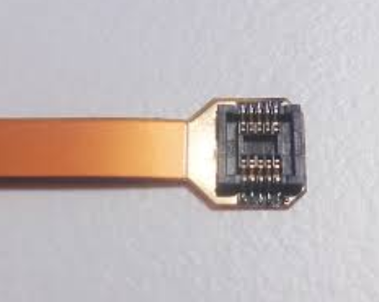
1.1 Flexible PCBs (Flex PCBs)
Flexible PCBs are made from polyimide (PI) or polyester films, which provide excellent thermal stability and mechanical flexibility. Unlike rigid PCBs, they can bend, twist, and fold without damaging the conductive traces.
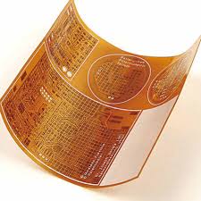
1.2 Flex-Foil PCBs
Flex-Foil PCBs take flexibility a step further by incorporating ultra-thin conductive foils (often copper) laminated onto flexible substrates. These PCBs are extremely lightweight and can conform to complex shapes, making them ideal for wearable electronics and compact devices.
2. Materials Used in Flex and Flex-Foil PCBs
2.1 Substrate Materials
- Polyimide (PI): The most common substrate due to its high thermal resistance (up to 400°C) and flexibility.
- Polyester (PET): A cost-effective alternative for less demanding applications.
- Liquid Crystal Polymer (LCP): Used in high-frequency applications due to its low dielectric loss.
2.2 Conductive Materials
- Copper Foil: The primary conductive layer, available in rolled annealed (RA) or electrodeposited (ED) forms.
- Silver or Gold Inks: Used in printed flexible circuits for specific applications.
2.3 Adhesives and Coatings
- Acrylic or Epoxy Adhesives: Bond layers together while maintaining flexibility.
- Coverlay Films: Protect circuits from environmental damage.
3. Manufacturing Process of Flex and Flex-Foil PCBs
3.1 Design and Layout
- CAD Software: Used to design flexible circuits, considering bend radius and mechanical stress.
- Layer Stackup: Determines the arrangement of conductive and insulating layers.
3.2 Fabrication Steps
- Substrate Preparation: Cleaning and laminating the base material.
- Circuit Patterning:
- Photolithography: Applying a photoresist, exposing to UV light, and etching unwanted copper.
- Laser Ablation: Precise removal of material for ultra-fine traces.
- Layer Bonding: Using adhesives or heat to combine multiple layers.
- Coverlay Application: Protecting the circuit with a flexible insulating layer.
- Cutting and Finishing: Laser or die-cutting to the final shape.
3.3 Advanced Techniques
- 3D Molding: Flex-Foil PCBs can be shaped into 3D forms for specialized applications.
- Stretchable Electronics: Emerging technology allowing circuits to stretch without breaking.
4. Advantages of Flex and Flex-Foil PCBs
4.1 Space and Weight Reduction
- Thinner and lighter than rigid PCBs, enabling compact designs in smartphones, wearables, and medical devices.
4.2 Enhanced Durability
- Resistant to vibrations, shocks, and bending, making them ideal for automotive and aerospace applications.
4.3 Improved Signal Integrity
- Reduced need for connectors, lowering signal loss and electromagnetic interference (EMI).
4.4 Cost Efficiency in Assembly
- Fewer interconnects reduce assembly time and potential failure points.
5. Applications of Flex and Flex-Foil PCBs
5.1 Consumer Electronics
- Smartphones & Tablets: Used in foldable displays and compact internals.
- Wearables: Fitness trackers and smartwatches benefit from flexible circuits.
5.2 Medical Devices
- Implantable Electronics: Flexible circuits conform to body contours.
- Diagnostic Equipment: Used in flexible sensors and endoscopes.
5.3 Automotive Industry
- Flexible Displays: Dashboard and infotainment systems.
- Sensor Arrays: Conforming to curved surfaces in vehicles.
5.4 Aerospace and Defense
- Satellites & Drones: Lightweight and durable circuits for harsh environments.
- Military Wearables: Flexible electronics for soldiers.
5.5 Industrial and IoT Applications
- Robotics: Flexible circuits allow for dynamic movement.
- Smart Packaging: Integrated sensors in flexible packaging.
6. Challenges and Future Trends
6.1 Current Challenges
- Higher Initial Costs: More complex manufacturing than rigid PCBs.
- Design Complexity: Requires expertise in flexible circuit layout.
6.2 Future Innovations
- Stretchable Electronics: For next-gen wearables and biomedical devices.
- Printed Flexible Circuits: Using conductive inks for low-cost production.
- Integration with AI & IoT: Smart flexible circuits for autonomous systems.
7. Conclusion
Flex and Flex-Foil PCBs represent a paradigm shift in electronics, enabling lighter, more durable, and highly adaptable circuit solutions. As technology advances, their applications will expand into foldable devices, advanced medical implants, and next-generation automotive systems.
Manufacturers and designers must continue innovating to overcome challenges and unlock the full potential of flexible electronics. The future of PCBs is flexible, dynamic, and revolutionary—ushering in a new era of electronic design.