
Aluminum PCB vs FR4: When to Choose Metal Core for LED Applications
If you’re designing an LED product, choosing between aluminum PCB and FR4 directly impacts LED lifespan and system cost. The wrong substrate leads to premature LED failure from overheating, while over-specifying metal core wastes budget.
This guide explains thermal, cost, and design differences between aluminum PCB and FR4 for LED applications. You will learn when FR4 suffices, when aluminum PCB becomes necessary, and how power density determines substrate selection.
Thermal Conductivity: The Core Difference
FR4 thermal conductivity is 0.25–0.3 W/m·K, functioning as thermal insulator. Heat removal relies on copper and thermal via structures. Aluminum PCB dielectric offers 1.0–10 W/m·K (typical 1.5–3.0 W/m·K), with aluminum base at 160–200 W/m·K providing integrated heat spreading.
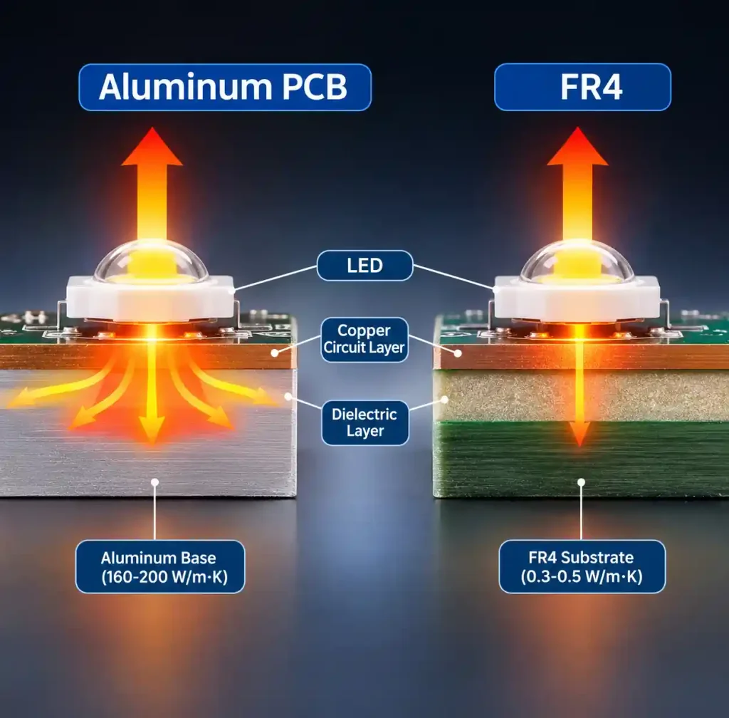
Testing shows high-power LEDs on FR4 experience junction temperature 20–30°C higher than aluminum PCB at identical power and ambient conditions. This temperature gap determines substrate selection for LED applications.
When FR4 Suffices for LED Applications
FR4 works for LEDs meeting specific power criteria:
| LED Type | Max Power per LED | Max Power Density | Thermal Via Requirements |
|---|---|---|---|
| Indicator LEDs | < 0.1W | < 0.5 W/cm² | Optional |
| Low-power signage | 0.1–0.5W | 0.5–1.0 W/cm² | 4–8 vias per LED pad |
| Mid-power arrays | 0.5–1.0W | 1.0–2.0 W/cm² | 8–16 vias per LED, heat sink required |
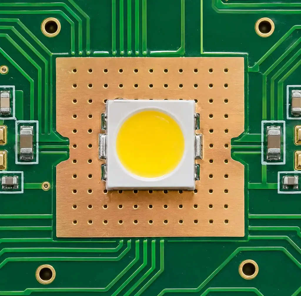
FR4 thermal optimization requires 0.3mm vias on 0.6–0.8mm spacing under LED pads, 2oz copper minimum, and 1.6mm board thickness. These optimizations reduce junction temperature 10–15°C versus basic designs.
When Aluminum PCB Becomes Necessary
Choose aluminum PCB when LED applications meet these conditions:
| Application Criteria | FR4 Limitation | Aluminum PCB Benefit |
|---|---|---|
| LED power > 1W | Junction temp > 125°C | 40–60% temp reduction |
| Power density > 2 W/cm² | Inadequate heat spreading | Integrated heat spreader |
| Ambient > 50°C | Reduced thermal headroom | Lower thermal resistance |
| Lifespan > 50,000 hrs | Lumen depreciation | Maintains L70 rating |
Application examples:
- Street lighting (50–150W, 3–5W per LED): Aluminum mandatory, -40°C to +60°C operation
- Commercial downlights (10–30W, 1–2W per LED): Aluminum for > 1.5W per LED
- Automotive lighting (20–40W, 2–5W per LED): Aluminum mandatory for thermal and vibration
- Indoor signage (0.2–0.5W per LED): FR4 standard, aluminum for outdoor high-density
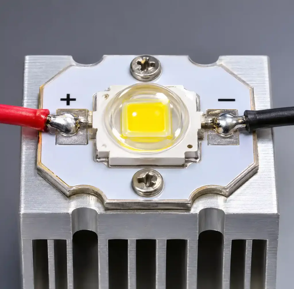
Andwin Circuits manufactures both metal core PCB and standard FR4 boards with thermal optimization for diverse LED applications.
Cost Analysis
| Cost Component | FR4 (1.6mm) | Aluminum PCB (1.5mm) | Multiplier |
|---|---|---|---|
| Material per m² | $8–15 | $25–50 | 2.5–4× |
| Fabrication | Standard | +20–50% | 1.2–1.5× |
| External heat sink | Often required | May eliminate | Variable |
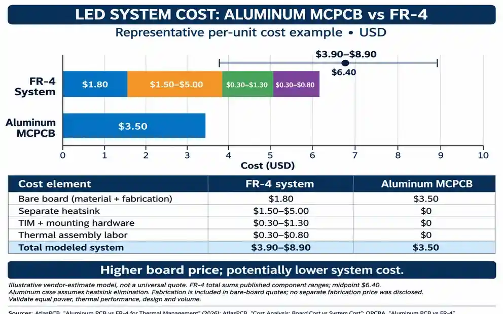
Aluminum PCB costs 2.5–4× more than FR4 material, but system cost analysis shows nuance. When aluminum eliminates separate heat sinks ($0.50–5.00), assembly complexity, or field failures, the premium justifies itself. Calculate break-even based on heat sink elimination and warranty costs.
Design Constraints
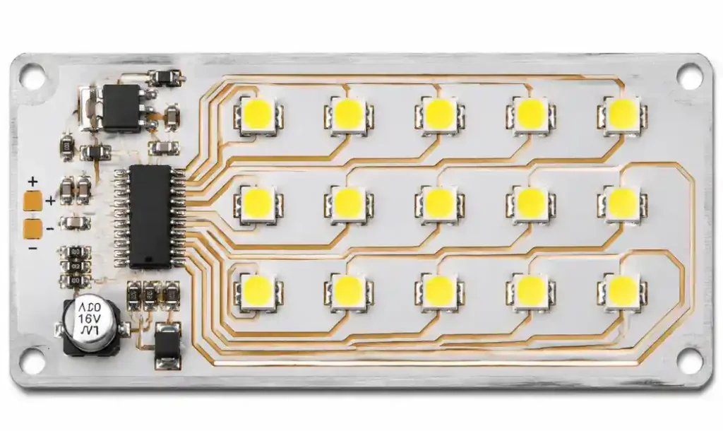
Aluminum PCB introduces specific limitations:
Electrical constraints:
- Single-sided circuit layer only (double-sided costs 3–5× more)
- No through-hole plating
- Complex routing requires jumpers
- All components mount on one side
Manufacturing considerations:
- CNC routing preferred over V-scoring
- Reflow profile identical to FR4
- Hand soldering requires higher wattage (80–100W)
- Thermal interface material needed between aluminum base and heat sink
Dielectric Layer Selection
| Dielectric Type | Thermal Conductivity | Breakdown Voltage | Cost | Application |
|---|---|---|---|---|
| Standard epoxy | 1.0–1.5 W/m·K | 3 kV | 1× | LED < 1W |
| High thermal | 2.0–3.0 W/m·K | 2.5 kV | 1.5× | LED 1–3W |
| Ceramic-filled | 3.0–4.0 W/m·K | 3 kV | 2× | LED > 3W |
Thickness options:
- 50μm: 1.5 kV breakdown, for < 48V systems
- 75μm: 2.5 kV breakdown, standard for 24–48V LED
- 100μm: 3–4 kV breakdown, for > 100V LED strings
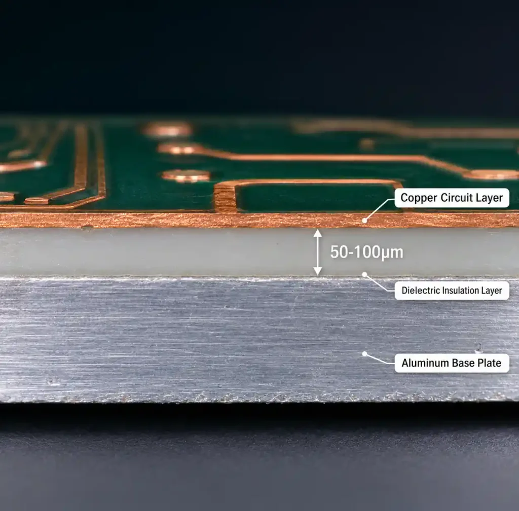
For 1–3W LEDs, 2.0–3.0 W/m·K dielectric balances thermal performance and cost. Thinner dielectric improves conductivity but reduces voltage isolation.
Decision Framework
Choose FR4 when ALL met:
- Power density < 1.0 W/cm²
- Individual LED < 0.5W
- Ambient < 50°C
- Multi-layer routing needed
- Budget constrained
Choose aluminum PCB when ANY met:
- Power density > 2.0 W/cm²
- Individual LED > 1.5W
- Ambient > 60°C
- Reliability > 50,000 hours
- Single-layer adequate
For intermediate cases (0.5–1.5W per LED, 1.0–2.0 W/cm²), perform junction temperature calculation using LED thermal resistance specs and maintain temperature below maximum rating with 10–20°C safety margin.
Frequently Asked Questions
Can I mix FR4 and aluminum PCB in the same product?
Yes. Hybrid designs use FR4 for control circuits and aluminum for LED arrays, connected via connectors or flex circuits. This optimizes cost by limiting aluminum use to high-power sections.
How much does aluminum PCB reduce LED junction temperature?
Testing shows 40–60% reduction versus FR4 at identical power. A 3W LED at 125°C on FR4 drops to 75–90°C on aluminum, significantly extending lifespan.
Does aluminum PCB eliminate heat sinks?
Not automatically. It improves heat spreading but whether heat sinks remain necessary depends on total power, enclosure design, and ambient temperature.
What LED power requires aluminum PCB?
Approximately 1–1.5W per LED for mid-power packages. Below 1W, FR4 with thermal vias suffices. Above 1.5W, aluminum becomes necessary.
Can I use aluminum PCB for double-sided LED?
Standard aluminum is single-sided. Double-sided exists but costs 3–5× standard. Consider FR4 or two separate aluminum PCBs mounted back-to-back.
How does aluminum affect LED lifespan?
Lower junction temperature extends lifespan exponentially. Every 10°C reduction approximately doubles L70 lifespan. A 30°C reduction extends life from 25,000 to 100,000+ hours.
Conclusion
Aluminum PCB versus FR4 for LED applications reduces to thermal requirements from power density and environment. FR4 remains cost-effective for LEDs below 1W where thermal vias provide adequate heat removal. Aluminum becomes necessary when LED power exceeds 1.5W or power density surpasses 2 W/cm², where its 5–30× superior thermal conductivity maintains safe junction temperature.
The decision extends beyond material cost to system economics including heat sinks, assembly complexity, and field reliability. Perform junction temperature analysis early to validate substrate choice. For intermediate power (0.5–1.5W per LED), thermal modeling determines whether optimized FR4 suffices or aluminum’s thermal performance justifies cost premium. Choose the substrate meeting your thermal requirements at lowest total system cost.