Best 6 layer pcb stackup
Optimizing Signal Integrity in 6 Layer PCB Stackup Designs
In the realm of printed circuit board (PCB) design, optimizing signal integrity is paramount, particularly in complex multilayer configurations such as a 6-layer PCB stackup. As electronic devices become increasingly sophisticated, the demand for efficient and reliable PCB designs has surged. A well-structured 6-layer PCB stackup not only enhances signal integrity but also minimizes electromagnetic interference (EMI) and crosstalk, which are critical for maintaining the performance and reliability of electronic systems.
To begin with, understanding the fundamental principles of a 6-layer PCB stackup is essential.
Typically, a 6-layer PCB consists of two outer layers and four inner layers. The outer layers are generally used for routing signals, while the inner layers are designated for power and ground planes. This configuration allows for a balanced distribution of signals and power, which is crucial for maintaining signal integrity. By strategically arranging these layers, designers can effectively manage impedance, reduce signal reflection, and minimize the risk of signal degradation.
One of the most effective stackup configurations for optimizing signal integrity in a 6-layer PCB involves the use of dedicated ground and power planes.
For instance, a common stackup might include signal layers on the top and bottom, with ground and power planes sandwiched between them. This arrangement not only provides a low-inductance path for return currents but also offers excellent shielding against EMI. Moreover, placing the ground plane adjacent to the signal layers helps to control the impedance and reduce the loop area, thereby minimizing the potential for crosstalk.
In addition to layer arrangement, the choice of materials plays a significant role in optimizing signal integrity.
High-frequency applications, in particular, benefit from materials with low dielectric constants and low loss tangents. These materials help to maintain signal speed and reduce signal loss, which is crucial for high-speed data transmission. Furthermore, selecting materials with consistent dielectric properties across the board ensures uniform signal propagation, thereby enhancing overall performance.
Transitioning to the topic of via design, it is important to note that vias can significantly impact signal integrity in a 6-layer PCB stackup.
Vias introduce parasitic inductance and capacitance, which can degrade signal quality. To mitigate these effects, designers often employ techniques such as back-drilling to remove unused via stubs, thereby reducing reflections and improving signal integrity. Additionally, using blind or buried vias can help to minimize the impact on signal paths, as they allow for more direct routing between layers.
Another critical aspect of optimizing signal integrity is the careful management of trace widths and spacing.
Maintaining consistent trace widths and ensuring adequate spacing between traces can prevent impedance mismatches and reduce the risk of crosstalk. Moreover, employing differential signaling techniques, where applicable, can further enhance signal integrity by providing better noise immunity and reducing EMI.
In conclusion, optimizing signal integrity in a 6-layer PCB stackup design requires a comprehensive approach that encompasses layer arrangement, material selection, via design, and trace management. By carefully considering these factors, designers can create PCB stackups that not only meet the demands of modern electronic devices but also ensure reliable and efficient performance. As technology continues to evolve, the importance of optimizing signal integrity in PCB designs will only grow, underscoring the need for innovative and effective design strategies.
Cost-Effective Strategies for 6 Layer PCB Stackup
When designing a 6-layer printed circuit board (PCB), achieving a balance between performance and cost-effectiveness is crucial. A well-structured stackup not only enhances the electrical performance but also optimizes manufacturing costs.
To begin with, understanding the fundamental structure of a 6-layer PCB is essential.
Typically, it consists of two outer layers and four inner layers, which can be configured to serve various functions such as signal routing, power distribution, and ground planes. The arrangement of these layers significantly impacts the board’s performance, particularly in terms of signal integrity and electromagnetic interference (EMI) control.
One cost-effective strategy is to utilize a symmetrical stackup.
Symmetry in the layer arrangement helps in minimizing warping during the manufacturing process, which can otherwise lead to increased production costs due to potential defects. A common symmetrical stackup might include two signal layers on the outermost surfaces, followed by ground and power planes, and two additional signal layers in the center. This configuration not only supports effective signal routing but also provides robust power distribution and EMI shielding.
Moreover, selecting the right materials is another critical aspect of cost management.
While high-performance materials can enhance the board’s capabilities, they also increase costs. Therefore, opting for standard FR-4 material, which offers a good balance between performance and cost, is often advisable for most applications. However, for high-frequency applications, where signal integrity is paramount, investing in materials with better dielectric properties might be necessary despite the higher cost.
In addition to material selection, the use of blind and buried vias can also influence the cost-effectiveness of a 6-layer PCB stackup.
While these vias can save space and improve signal integrity by reducing the length of signal paths, they are more expensive to implement than through-hole vias. Therefore, their use should be carefully considered and limited to areas where they provide significant benefits.
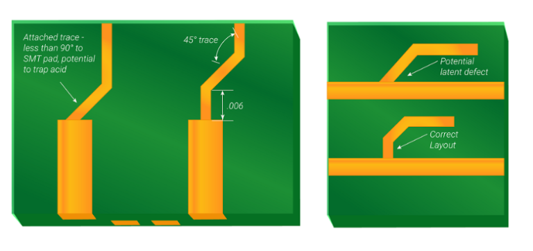
Furthermore, optimizing the trace width and spacing can lead to cost savings.
By adhering to the manufacturer’s design rules and capabilities, designers can avoid unnecessary complexity that might increase production costs. For instance, maintaining a consistent trace width and spacing not only simplifies the manufacturing process but also reduces the likelihood of errors, thereby lowering the overall cost.
Another strategy involves the careful planning of power and ground planes.
By dedicating entire layers to power and ground, designers can ensure a low-impedance path for power distribution, which is crucial for maintaining signal integrity. This approach also aids in effective heat dissipation, which can reduce the need for additional cooling solutions, thereby saving costs.
Finally, collaboration with the PCB manufacturer during the design phase can yield significant cost benefits.
Manufacturers can provide valuable insights into the most cost-effective design practices and materials, helping to avoid costly revisions later in the process. By leveraging their expertise, designers can ensure that the stackup is not only optimized for performance but also for manufacturability and cost.
In conclusion, a cost-effective 6-layer PCB stackup requires a strategic approach that considers symmetry, material selection, via usage, trace optimization, and collaboration with manufacturers. By carefully balancing these factors, designers can achieve a PCB that meets performance requirements without exceeding budget constraints.
Thermal Management Techniques in 6 Layer PCB Stackup
In the realm of printed circuit board (PCB) design, the 6-layer PCB stackup is a popular choice due to its balance between complexity and cost-effectiveness. One of the critical aspects of designing a 6-layer PCB is effective thermal management, which ensures the reliability and longevity of the electronic components. As electronic devices become more compact and powerful, managing heat dissipation becomes increasingly crucial. Therefore, understanding the thermal management techniques applicable to a 6-layer PCB stackup is essential for engineers and designers.
To begin with, the choice of materials plays a significant role in thermal management.
The dielectric materials used in the PCB layers should have good thermal conductivity to facilitate heat dissipation. FR-4, a common material used in PCBs, has moderate thermal conductivity. However, for applications requiring superior thermal performance, materials with higher thermal conductivity, such as metal-core PCBs or ceramics, may be considered. Additionally, the copper thickness in the PCB layers can be adjusted to enhance heat dissipation. Thicker copper layers can conduct heat more effectively, thus reducing the thermal resistance of the PCB.
Moreover, the arrangement of layers in a 6-layer PCB stackup can significantly impact thermal management.
A typical 6-layer stackup might include signal layers, power planes, and ground planes. By strategically placing power and ground planes adjacent to each other, designers can create a heat spreader effect, which helps in distributing heat more evenly across the board. This configuration not only aids in thermal management but also improves the electrical performance by reducing electromagnetic interference (EMI).
Furthermore, the use of thermal vias is another effective technique for managing heat in a 6-layer PCB.
Thermal vias are plated holes that connect the different layers of the PCB, allowing heat to be transferred from the surface to the inner layers or vice versa. By placing thermal vias near heat-generating components, designers can create a path for heat to escape, thereby preventing localized hotspots. The size, number, and placement of these vias are crucial factors that need to be optimized to achieve efficient thermal management.
In addition to these structural techniques, the layout of components on the PCB also influences thermal performance.
Components that generate significant amounts of heat should be placed in areas where heat can be dissipated effectively, such as near the edges of the board or in proximity to heat sinks. Grouping components with similar thermal characteristics can also help in managing heat more efficiently. Moreover, maintaining adequate spacing between components ensures that there is sufficient airflow, which aids in cooling.
Lastly, the integration of external cooling solutions, such as heat sinks and fans, can further enhance the thermal management of a 6-layer PCB.
Heat sinks can be attached to high-power components to increase the surface area for heat dissipation. Fans can be used to improve airflow across the PCB, thereby reducing the overall temperature. However, these solutions should be considered in conjunction with the internal thermal management techniques to achieve optimal results.
In conclusion, effective thermal management in a 6-layer PCB stackup involves a combination of material selection, layer arrangement, use of thermal vias, component layout, and external cooling solutions. By carefully considering these factors, designers can ensure that their PCBs operate efficiently and reliably, even under demanding conditions. As technology continues to advance, the importance of thermal management in PCB design will only grow, making it a critical area of focus for engineers and designers alike.

Innovative Materials for Enhanced Performance in 6 Layer PCB Stackup
In the realm of modern electronics, the demand for compact, efficient, and high-performance devices has led to significant advancements in printed circuit board (PCB) technology. Among these advancements, the development of innovative materials for 6-layer PCB stackups has emerged as a critical factor in enhancing the performance and reliability of electronic devices. As the complexity of electronic circuits increases, the need for effective signal integrity, thermal management, and electromagnetic compatibility becomes paramount. Consequently, selecting the right materials for a 6-layer PCB stackup is essential to meet these demands.
To begin with, the choice of substrate material plays a pivotal role in determining the overall performance of a 6-layer PCB.
Traditionally, FR-4, a glass-reinforced epoxy laminate, has been the go-to material due to its cost-effectiveness and satisfactory performance in many applications. However, as electronic devices become more sophisticated, the limitations of FR-4, such as its relatively high dielectric constant and loss tangent, have prompted the exploration of alternative materials. For instance, high-frequency laminates, such as Rogers and Taconic materials, offer lower dielectric constants and loss tangents, making them ideal for high-speed and RF applications. These materials ensure minimal signal loss and improved signal integrity, which are crucial for maintaining the performance of complex circuits.
In addition to substrate materials, the choice of copper foil is another critical consideration in a 6-layer PCB stackup.
The thickness and type of copper foil can significantly impact the board’s electrical and thermal performance. For high-current applications, thicker copper layers are preferred to handle the increased current load without overheating. Moreover, the use of low-profile or ultra-low-profile copper foils can reduce signal loss and improve impedance control, which is essential for high-frequency applications. These foils provide a smoother surface, reducing the skin effect and ensuring better signal transmission.
Furthermore, the incorporation of advanced dielectric materials in the stackup can enhance the thermal management capabilities of the PCB.
As electronic devices continue to shrink in size, efficient heat dissipation becomes increasingly important to prevent overheating and ensure longevity. Materials with high thermal conductivity, such as ceramic-filled dielectrics, can effectively dissipate heat away from critical components, maintaining optimal operating temperatures. This is particularly beneficial in applications where high power density and thermal management are of utmost concern.
Moreover, the use of innovative materials in the prepreg layers of a 6-layer PCB stackup can further enhance its performance.
Prepregs, which are sheets of fiberglass impregnated with resin, serve as the bonding layers between the copper and core materials. By selecting prepregs with tailored dielectric properties, designers can achieve better impedance control and signal integrity. Additionally, prepregs with enhanced thermal properties can contribute to improved heat dissipation, further bolstering the board’s reliability.
In conclusion, the selection of innovative materials for a 6-layer PCB stackup is a multifaceted process that requires careful consideration of various factors, including signal integrity, thermal management, and electromagnetic compatibility. By leveraging advanced substrate materials, copper foils, dielectric materials, and prepregs, designers can create PCBs that meet the demanding requirements of modern electronic devices. As technology continues to evolve, the development and adoption of new materials will undoubtedly play a crucial role in pushing the boundaries of PCB performance and enabling the next generation of electronic innovations.