Flexible PCB Current Carrying Capacity: A Comprehensive Guide
Introduction to Flexible PCB Current Capacity
Flexible printed circuit boards (flex PCBs) have become increasingly popular in modern electronics due to their ability to conform to different shapes and withstand repeated bending. However, one critical aspect that engineers must carefully consider is the current carrying capacity of these flexible circuits. Unlike traditional rigid PCBs, flex circuits present unique challenges in thermal management and current distribution due to their thin, flexible nature.
The current carrying capacity of a flex PCB refers to the maximum amount of electrical current that can safely pass through its conductors without causing excessive heating, degradation of materials, or failure of the circuit. This parameter is crucial for ensuring reliability, especially in applications where flex circuits are subjected to dynamic flexing or high-temperature environments.
Understanding the factors that influence current capacity in flex PCBs is essential for designers to create robust, reliable circuits that meet application requirements while maintaining safety margins. This article will explore the key considerations, calculation methods, and design techniques for optimizing current carrying capacity in flexible printed circuits.
Factors Affecting Current Carrying Capacity in Flex PCBs
1. Conductor Material and Thickness
The base material of the conductive traces significantly impacts current capacity. Most flex PCBs use rolled annealed copper due to its excellent flexibility and conductivity. The current carrying capacity increases with:
- Thicker copper layers (common weights: 1/2 oz, 1 oz, 2 oz)
- Higher purity copper (typically 99.9% pure)
- Proper surface finishes (electroless nickel immersion gold, tin, or other protective coatings)
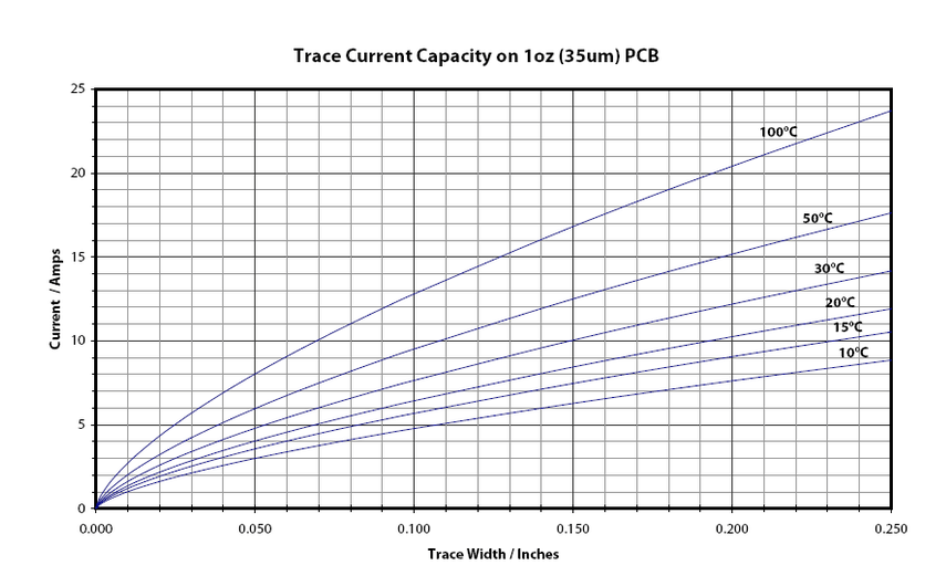
2. Trace Width and Geometry
Wider traces can carry more current, but the relationship isn’t linear due to thermal considerations. Key aspects include:
- Minimum width requirements based on current needs
- Trace thickness to width ratio
- Corner and bend radius effects on current distribution
- Spacing between adjacent traces to prevent thermal coupling
3. Dielectric Materials and Thermal Properties
The insulating materials surrounding the conductors affect heat dissipation:
- Polyimide (most common) has good thermal stability up to 300°C
- Adhesive vs. adhesive-less constructions affect thermal resistance
- Dielectric thickness influences heat transfer to environment
- Thermal conductivity of the base material
4. Environmental Conditions
Operating conditions dramatically impact current ratings:
- Ambient temperature (derating required at elevated temperatures)
- Airflow or cooling mechanisms
- Confined spaces vs. open air environments
- Altitude (affects cooling efficiency)
5. Dynamic vs. Static Applications
Flex circuits may be classified as:
- Static (installed and not moved during operation)
- Dynamic (subjected to repeated flexing)
Dynamic applications require more conservative current ratings due to: - Mechanical stress on conductors
- Potential for microcracks developing over time
- Increased resistance from repeated deformation
Calculation Methods for Current Capacity
IPC-2152 Standard
The IPC-2152 standard provides guidelines for determining current carrying capacity in printed circuit boards, including flex circuits. The standard considers:
- Internal vs. external traces (different cooling characteristics)
- Copper weight and trace geometry
- Temperature rise limits
- Adjacent trace effects
The basic calculation approach involves:
- Determining allowable temperature rise (ΔT)
- Calculating trace cross-sectional area
- Using standard charts or formulas to find current capacity
- Applying appropriate derating factors
Empirical Formulas
For quick estimates, engineers often use modified versions of the basic current formula:
I = k × ΔT^0.44 × A^0.725
Where:
- I = current in amps
- k = correction factor (0.048 for external traces, 0.024 for internal)
- ΔT = temperature rise in °C
- A = cross-sectional area in mils²
For flex PCBs, additional derating factors (0.5-0.8) are often applied to account for flexible materials and potential dynamic operation.
Finite Element Analysis (FEA)
For critical applications, FEA thermal modeling provides the most accurate predictions by:
- Simulating heat generation and dissipation
- Accounting for complex geometries
- Modeling specific environmental conditions
- Analyzing multi-layer configurations
Design Techniques to Improve Current Capacity
1. Trace Optimization
- Use teardrop shapes at connections to reduce stress concentrations
- Implement curved corners instead of sharp angles
- Consider hourglass shapes in bending areas to distribute stress
- Increase width in high-current sections when possible
2. Multi-layer Approaches
- Distribute current across multiple parallel traces
- Use stacked vias for interlayer connections
- Implement power and ground planes where possible
- Consider asymmetric constructions for improved heat dissipation
3. Thermal Management Strategies
- Incorporate thermal relief patterns
- Add copper pours for heat spreading
- Use stiffeners in high-current areas
- Consider metal-backed constructions for power applications
- Implement thermal vias to transfer heat between layers
4. Material Selection
- Choose higher temperature rated materials (up to 300°C)
- Consider adhesiveless constructions for better thermal performance
- Select materials with higher thermal conductivity
- Use thicker copper when dynamic flexing isn’t critical
Testing and Validation
1. Prototype Testing
Essential tests include:
- Temperature rise measurements at various currents
- IR thermography to identify hot spots
- Continuity testing during and after flex cycling
- Microsection analysis to inspect for damage
2. Accelerated Life Testing
- Thermal cycling to simulate environmental stresses
- Dynamic flex testing under load
- High-temperature operation testing
- Humidity and environmental exposure tests
3. In-Situ Monitoring
For critical applications:
- Embed temperature sensors
- Implement current monitoring circuits
- Use strain gauges in flex areas
- Perform periodic resistance measurements
Application-Specific Considerations
1. High-Frequency Applications
- Skin effect becomes significant at high frequencies
- May require special attention to surface roughness
- Current distribution across trace cross-section changes
2. Automotive Applications
- Must withstand wide temperature ranges (-40°C to +150°C)
- Vibration and mechanical stress requirements
- Long-term reliability expectations (15+ years)
3. Medical Devices
- Strict safety requirements
- Often need ultra-thin constructions
- May require special materials for biocompatibility
4. Aerospace and Defense
- Extreme environmental conditions
- High reliability demands
- Radiation and outgassing considerations
Future Trends and Developments
1. Advanced Materials
- Graphene and carbon nanotube-based conductors
- Metal matrix composites for improved thermal performance
- Shape memory alloys for self-healing circuits
2. 3D Printed Electronics
- Direct printing of conductors with optimized geometries
- Embedded cooling channels
- Graded material properties
3. Intelligent Flex Circuits
- Integrated temperature sensors
- Self-regulating conductors
- Active cooling elements
4. Improved Simulation Tools
- AI-assisted thermal modeling
- Multi-physics simulation integrating electrical, thermal, and mechanical aspects
- Predictive analytics for lifetime estimation
Conclusion
The current carrying capacity of flexible PCBs is a complex parameter that requires careful consideration of multiple interacting factors. Unlike rigid boards, flex circuits introduce additional variables related to mechanical stress, material fatigue, and unique thermal management challenges. Designers must balance electrical requirements with mechanical reliability, especially in dynamic flexing applications.
By understanding the fundamental principles, applying appropriate calculation methods, and implementing optimized design techniques, engineers can develop flex circuit solutions that meet both current capacity requirements and long-term reliability goals. As flexible electronics continue to evolve, new materials and technologies will further expand the capabilities of flex PCBs in high-current applications.
Proper design, thorough testing, and application of appropriate safety margins remain essential for ensuring that flex circuits perform reliably throughout their intended service life. The information presented in this article provides a foundation for making informed decisions about current carrying capacity in flexible PCB designs.