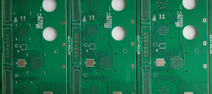
High voltage pcb trace spacing
Design Techniques for High-Frequency PCBs
Designing high-frequency printed circuit boards (PCBs) requires a meticulous approach to ensure optimal performance and reliability. As the frequency of operation increases, the challenges associated with signal integrity, electromagnetic interference (EMI), and thermal management become more pronounced. Therefore, employing specific design techniques is crucial to mitigate these issues and achieve the desired functionality.
One of the primary considerations in high-frequency PCB design is the selection of appropriate materials.
Traditional FR-4 substrates may not suffice due to their higher dielectric losses at elevated frequencies. Instead, materials such as Rogers, Taconic, or other low-loss laminates are preferred. These materials exhibit lower dielectric constants and dissipation factors, which help in maintaining signal integrity by reducing signal attenuation and phase distortion.
Another critical aspect is the layout of the PCB traces.
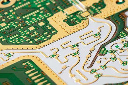
At high frequencies, the physical dimensions of the traces become comparable to the wavelength of the signals, making them susceptible to transmission line effects. To address this, controlled impedance traces are employed. This involves designing the trace width, spacing, and the distance from the reference plane to ensure a consistent impedance, typically 50 ohms. Microstrip and stripline configurations are commonly used to achieve controlled impedance, with microstrip traces being placed on the outer layers and striplines sandwiched between inner layers.
Signal integrity is further enhanced by minimizing the length of high-frequency traces and avoiding sharp bends.
Right-angle bends can cause signal reflections and impedance discontinuities, leading to signal degradation. Instead, gradual curves or 45-degree bends are recommended. Additionally, differential signaling is often utilized for high-speed data transmission. Differential pairs should be routed closely together with consistent spacing to maintain the differential impedance and reduce common-mode noise.
Ground planes play a pivotal role in high-frequency PCB design.
A solid ground plane provides a low-inductance return path for signals, reducing EMI and crosstalk. It is essential to ensure that the ground plane is continuous and unbroken, especially under high-frequency traces. Stitching vias can be used to connect multiple ground planes, further enhancing signal integrity. Moreover, power planes should be carefully designed to minimize noise coupling and voltage drops.
Thermal management is another crucial consideration.
High-frequency components often generate significant heat, which can affect performance and reliability. Effective thermal vias, heat sinks, and thermal pads should be incorporated to dissipate heat efficiently. Additionally, the placement of components should be optimized to prevent hotspots and ensure even heat distribution.
The use of simulation tools is indispensable in high-frequency PCB design.
Electromagnetic simulation software can predict the behavior of high-frequency signals, allowing designers to identify potential issues and optimize the layout before fabrication. Time-domain reflectometry (TDR) and vector network analyzers (VNA) are also valuable tools for measuring and validating the impedance and signal integrity of the PCB.
In conclusion, designing high-frequency PCBs necessitates a comprehensive understanding of material properties, trace layout, signal integrity, grounding, and thermal management. By carefully selecting materials, employing controlled impedance traces, maintaining continuous ground planes, and utilizing simulation tools, designers can effectively address the challenges associated with high-frequency operation. These techniques ensure that the PCB performs reliably and efficiently, meeting the stringent requirements of modern high-frequency applications.

Material Selection for High-Frequency PCB Applications
When designing high-frequency printed circuit boards (PCBs), the selection of materials plays a crucial role in ensuring optimal performance and reliability. High-frequency applications, typically defined as those operating above 1 GHz, demand materials that can handle the unique challenges posed by such environments. These challenges include signal integrity, thermal management, and mechanical stability. Therefore, understanding the properties of various materials and their suitability for high-frequency applications is essential for engineers and designers.
One of the primary considerations in material selection for high-frequency PCBs is the dielectric constant (Dk).
The dielectric constant affects the speed at which signals propagate through the PCB material. Materials with a low and stable dielectric constant are preferred because they minimize signal loss and ensure consistent signal transmission. Common materials used in high-frequency PCBs include PTFE (Polytetrafluoroethylene), ceramic-filled PTFE, and hydrocarbon-based laminates. PTFE, often known by the brand name Teflon, is particularly favored for its low dielectric constant and excellent thermal stability.
In addition to the dielectric constant, the dissipation factor (Df) is another critical parameter.
The dissipation factor measures the energy loss as heat within the dielectric material. A low dissipation factor is desirable for high-frequency applications because it reduces signal attenuation and power loss. Materials such as Rogers RO3000 and RO4000 series laminates are known for their low dissipation factors, making them suitable for high-frequency circuits.
Thermal management is another vital aspect to consider when selecting materials for high-frequency PCBs.
High-frequency circuits often generate significant amounts of heat, which can affect the performance and longevity of the PCB. Materials with high thermal conductivity are essential to dissipate heat effectively. Ceramic-filled PTFE materials, for instance, offer excellent thermal conductivity while maintaining low dielectric constants and dissipation factors. Additionally, materials with high glass transition temperatures (Tg) are preferred as they can withstand higher operating temperatures without degrading.
Mechanical stability is equally important in high-frequency PCB applications.
The materials must maintain their structural integrity under various environmental conditions, including temperature fluctuations and mechanical stress. Materials with low coefficients of thermal expansion (CTE) are ideal as they minimize dimensional changes with temperature variations, ensuring reliable performance. For example, hydrocarbon-based laminates exhibit low CTE values, making them suitable for high-frequency applications that require mechanical robustness.
Furthermore, the choice of copper cladding is also significant in high-frequency PCB design.
The surface roughness of the copper can impact signal integrity, especially at higher frequencies. Smooth copper surfaces are preferred as they reduce signal loss and improve overall performance. Advanced manufacturing techniques, such as rolled annealed copper, can provide the necessary surface smoothness for high-frequency applications.
In conclusion, selecting the appropriate materials for high-frequency PCB applications involves a careful balance of various factors, including dielectric constant, dissipation factor, thermal management, mechanical stability, and copper cladding. By understanding the properties and performance characteristics of different materials, engineers and designers can make informed decisions that enhance the performance and reliability of high-frequency circuits. As technology continues to advance and the demand for high-frequency applications grows, the importance of material selection in PCB design will only become more critical.

Signal Integrity Challenges in High-Frequency PCB Design
High-frequency printed circuit boards (PCBs) are integral to modern electronic devices, particularly in applications such as telecommunications, radar systems, and high-speed computing. However, designing these PCBs presents unique challenges, especially concerning signal integrity. Signal integrity refers to the quality and reliability of electrical signals as they travel through the PCB. In high-frequency applications, maintaining signal integrity is paramount, as even minor disruptions can lead to significant performance degradation.
One of the primary challenges in high-frequency PCB design is managing signal loss.
Signal loss occurs due to the inherent resistance of the conductive materials and the dielectric losses in the substrate. As frequencies increase, these losses become more pronounced, leading to attenuation of the signal. To mitigate this, designers often use low-loss materials such as PTFE (polytetrafluoroethylene) or Rogers laminates, which have lower dielectric constants and dissipation factors compared to traditional FR-4 substrates. These materials help reduce signal loss, but they also come with higher costs and more complex manufacturing processes.
Another critical issue is signal reflection, which can occur at impedance discontinuities along the transmission path.
Impedance mismatches can cause portions of the signal to be reflected back towards the source, resulting in signal degradation and potential data errors. To address this, designers must carefully control the impedance of the transmission lines by maintaining consistent trace widths, spacing, and using appropriate termination techniques. Additionally, employing differential signaling can help minimize the impact of reflections by using pairs of traces to carry complementary signals, thereby enhancing noise immunity and signal integrity.
Crosstalk is another significant concern in high-frequency PCB design.
Crosstalk refers to the unwanted coupling of signals between adjacent traces, which can lead to interference and signal distortion. As frequencies increase, the potential for crosstalk also rises due to the closer proximity of traces and the higher energy of the signals. To combat crosstalk, designers can implement strategies such as increasing the spacing between traces, using ground planes to provide shielding, and routing high-frequency signals on different layers to minimize interaction.
Electromagnetic interference (EMI) is also a major challenge in maintaining signal integrity.
High-frequency signals can radiate electromagnetic energy, which can interfere with other components and systems. To reduce EMI, designers can use techniques such as proper grounding, shielding, and the use of decoupling capacitors to filter out high-frequency noise. Additionally, careful layout planning, such as avoiding sharp bends in traces and maintaining short signal paths, can help minimize EMI.
Thermal management is another aspect that cannot be overlooked in high-frequency PCB design.
High-frequency operation often results in increased power dissipation, which can lead to thermal issues if not properly managed. Excessive heat can affect the performance and reliability of the PCB, leading to signal integrity problems. Effective thermal management strategies include using thermal vias, heat sinks, and ensuring adequate airflow to dissipate heat away from critical components.
In conclusion, maintaining signal integrity in high-frequency PCB design is a multifaceted challenge that requires careful consideration of various factors. By addressing issues such as signal loss, reflection, crosstalk, EMI, and thermal management, designers can ensure the reliable performance of high-frequency PCBs. As technology continues to advance and the demand for high-speed applications grows, the importance of mastering these challenges will only become more critical.

Advanced Manufacturing Processes for High-Frequency PCBs
High-frequency printed circuit boards (PCBs) are integral to the performance of modern electronic devices, particularly in applications requiring rapid signal transmission and minimal signal loss. The advanced manufacturing processes for high-frequency PCBs are crucial in ensuring that these boards meet the stringent requirements of high-speed and high-frequency applications. These processes involve meticulous material selection, precise fabrication techniques, and rigorous testing protocols to achieve optimal performance.
To begin with, the choice of materials is paramount in the manufacturing of high-frequency PCBs.
Unlike standard PCBs, which typically use FR-4 material, high-frequency PCBs often employ specialized substrates such as Rogers, Teflon, or ceramic-filled laminates. These materials possess superior dielectric properties, which are essential for maintaining signal integrity at high frequencies. The low dielectric constant and low dissipation factor of these materials minimize signal loss and ensure efficient signal propagation. Additionally, the thermal stability of these substrates is critical, as high-frequency applications often generate significant heat.
Once the appropriate materials are selected, the fabrication process must be executed with precision.
One of the key steps in this process is the etching of the copper traces. For high-frequency PCBs, the width and spacing of these traces are meticulously controlled to prevent signal interference and crosstalk. Advanced photolithography techniques are employed to achieve the fine line resolution required for these intricate designs. Moreover, the use of laser direct imaging (LDI) technology allows for greater accuracy and consistency in the patterning process, further enhancing the performance of the PCB.
Another critical aspect of the manufacturing process is the application of the solder mask.
In high-frequency PCBs, the solder mask not only protects the copper traces from oxidation and environmental damage but also plays a role in controlling the impedance of the traces. The thickness and uniformity of the solder mask layer are carefully monitored to ensure that it does not adversely affect the electrical properties of the PCB. Additionally, the use of advanced solder mask materials with low dielectric constants can further improve the performance of high-frequency PCBs.
The final stages of the manufacturing process involve the assembly and testing of the high-frequency PCBs.
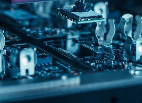
Surface mount technology (SMT) is commonly used for component placement, as it allows for higher component density and better electrical performance. The soldering process must be carefully controlled to prevent thermal damage to the sensitive high-frequency components. Once assembled, the PCBs undergo rigorous testing to verify their performance. This includes impedance testing, signal integrity analysis, and thermal cycling tests to ensure that the PCBs can withstand the demanding conditions of high-frequency applications.
In conclusion, the advanced manufacturing processes for high-frequency PCBs are essential in producing boards that meet the exacting standards of modern electronic devices. From the careful selection of materials to the precise fabrication techniques and rigorous testing protocols, each step in the process is designed to optimize the performance of the PCB. As technology continues to evolve and the demand for high-speed, high-frequency applications grows, the importance of these advanced manufacturing processes will only increase, driving further innovation and improvement in the field of high-frequency PCBs.

