Introduction to 2-Layer PCB Design and Manufacturing
Printed Circuit Boards (PCBs) are the backbone of modern electronics, providing a platform for mounting and interconnecting electronic components. Among the various types of PCBs, the 2-layer PCB is one of the most commonly used due to its simplicity, cost-effectiveness, and versatility. This article delves into the design, manufacturing, and applications of 2-layer PCBs, providing a comprehensive overview for engineers, hobbyists, and anyone interested in electronics.
What is a 2-Layer PCB?
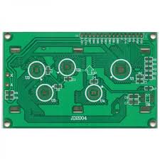
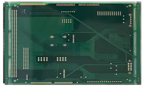
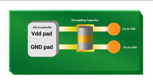
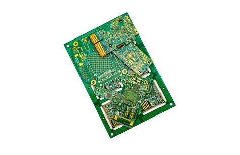
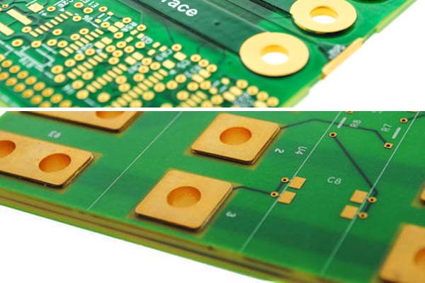
A 2-layer PCB, as the name suggests, consists of two layers of conductive material, typically copper, separated by an insulating substrate. The top and bottom layers are used to route electrical signals, while the substrate provides mechanical support and electrical insulation. The two layers are connected through vias, which are small holes drilled through the substrate and plated with conductive material to establish electrical connections between the layers.
Advantages of 2-Layer PCBs
- Cost-Effective: 2-layer PCBs are generally less expensive to manufacture compared to multi-layer PCBs (4-layer, 6-layer, etc.). This makes them an attractive option for simple electronic devices and prototypes.
- Simpler Design Process: Designing a 2-layer PCB is less complex than designing multi-layer PCBs. The reduced number of layers simplifies the routing process, making it easier for beginners to design their own PCBs.
- Faster Turnaround Time: The manufacturing process for 2-layer PCBs is quicker than for multi-layer PCBs. This is because fewer layers mean fewer steps in the fabrication process, leading to faster production times.
- Adequate for Many Applications: For many electronic devices, especially those with low to moderate complexity, a 2-layer PCB provides sufficient routing space and functionality. This includes consumer electronics, automotive systems, and industrial controls.

Design Considerations for 2-Layer PCBs
Designing a 2-layer PCB requires careful planning to ensure optimal performance and manufacturability. Below are some key considerations:
1. Component Placement
Proper component placement is crucial for efficient routing and minimizing signal interference. Components should be placed in a way that minimizes the length of traces, especially for high-speed signals. Placing components on both the top and bottom layers can help distribute the routing density and reduce the chances of signal crosstalk.
2. Routing
Routing on a 2-layer PCB involves connecting components using traces on both the top and bottom layers. It’s important to plan the routing to avoid long traces, which can introduce signal delays and increase the risk of electromagnetic interference (EMI). Using vias to switch between layers can help optimize the routing, but excessive use of vias can increase manufacturing costs and complexity.
3. Power and Ground Planes
In a 2-layer PCB, it’s common to dedicate one layer (usually the bottom layer) as a ground plane and the other layer for signal routing. This helps in reducing noise and providing a stable reference for signals. If possible, a small portion of the top layer can also be used as a power plane to distribute power efficiently.
4. Signal Integrity
Signal integrity is a critical consideration, especially for high-speed circuits. To minimize signal reflections and crosstalk, it’s important to maintain consistent trace widths and avoid sharp bends in the traces. Additionally, keeping high-speed signals away from noisy components (such as power supplies) can help maintain signal integrity.
5. Thermal Management
Heat dissipation is an important factor in PCB design, especially for power-hungry components. In a 2-layer PCB, thermal vias can be used to transfer heat from the top layer to the bottom layer, where it can be dissipated more effectively. Proper placement of heat-generating components and the use of thermal relief pads can also help manage heat.
6. Manufacturing Constraints
When designing a 2-layer PCB, it’s important to consider the manufacturing constraints, such as minimum trace width, minimum via size, and clearance between traces. These constraints vary depending on the PCB manufacturer, so it’s essential to consult their design guidelines before finalizing the layout.
Manufacturing Process of 2-Layer PCBs
The manufacturing process for 2-layer PCBs involves several steps, each of which must be carefully executed to ensure the final product meets the required specifications. Below is an overview of the typical manufacturing process:
1. Design and Layout
The first step in manufacturing a 2-layer PCB is to create the design and layout using PCB design software. The design includes the placement of components, routing of traces, and placement of vias. Once the design is complete, it is exported in a format (such as Gerber files) that can be used by the PCB manufacturer.
2. Material Selection
The base material for a 2-layer PCB is typically a fiberglass-reinforced epoxy laminate, known as FR-4. The thickness of the substrate and the copper layers can vary depending on the application. The choice of material affects the PCB’s mechanical strength, thermal performance, and electrical properties.
3. Printing the Circuit Pattern
The circuit pattern is printed onto the copper layers using a photolithographic process. A photosensitive film is applied to the copper layers, and the circuit pattern is exposed onto the film using UV light. The exposed areas are then etched away, leaving behind the desired copper traces.
4. Drilling
Holes are drilled through the PCB to create vias and mounting holes for components. The drilling process must be precise to ensure that the holes are properly aligned with the circuit pattern. After drilling, the holes are plated with conductive material to establish electrical connections between the layers.
5. Plating and Etching
The PCB undergoes a plating process to add a thin layer of copper to the walls of the drilled holes, creating conductive vias. The entire board is then etched to remove any unwanted copper, leaving behind only the desired circuit traces.
6. Solder Mask Application
A solder mask is applied to the PCB to protect the copper traces from oxidation and prevent solder bridges during assembly. The solder mask is typically green, but other colors are also available. Openings in the solder mask are created where components will be soldered.
7. Silkscreen Printing
A silkscreen layer is printed onto the PCB to add labels, component identifiers, and other markings. This layer helps during the assembly process by providing visual guidance for component placement.
8. Surface Finish
The final step in the manufacturing process is the application of a surface finish to the exposed copper areas. Common surface finishes include HASL (Hot Air Solder Leveling), ENIG (Electroless Nickel Immersion Gold), and OSP (Organic Solderability Preservative). The surface finish protects the copper from oxidation and improves solderability.

Applications of 2-Layer PCBs
2-layer PCBs are used in a wide range of applications, from simple consumer electronics to more complex industrial systems. Some common applications include:
- Consumer Electronics: Devices such as smartphones, tablets, and laptops often use 2-layer PCBs for their internal circuitry. While more complex devices may require multi-layer PCBs, many simpler consumer electronics can be effectively designed with 2-layer PCBs.
- Automotive Systems: 2-layer PCBs are commonly used in automotive electronics, such as engine control units (ECUs), infotainment systems, and sensors. The robustness and cost-effectiveness of 2-layer PCBs make them suitable for the demanding environment of automotive applications.
- Industrial Controls: Industrial control systems, such as PLCs (Programmable Logic Controllers) and motor controllers, often use 2-layer PCBs. These systems require reliable and durable PCBs that can withstand harsh industrial environments.
- Medical Devices: Many medical devices, such as patient monitors and diagnostic equipment, use 2-layer PCBs. The simplicity and reliability of 2-layer PCBs make them a good choice for medical applications where safety and performance are critical.
- IoT Devices: The Internet of Things (IoT) has led to the proliferation of small, low-power devices that often use 2-layer PCBs. These devices require compact and cost-effective PCBs that can support wireless communication and sensor integration.
Conclusion
2-layer PCBs are a fundamental building block in the world of electronics, offering a balance between simplicity, cost-effectiveness, and functionality. While they may not be suitable for the most complex electronic systems, they are more than adequate for a wide range of applications, from consumer electronics to industrial controls. By understanding the design considerations and manufacturing process, engineers and hobbyists can effectively utilize 2-layer PCBs to bring their electronic projects to life.
As technology continues to evolve, the demand for 2-layer PCBs is likely to remain strong, particularly in applications where cost and simplicity are paramount. Whether you’re designing a simple prototype or a mass-produced electronic device, the 2-layer PCB is a versatile and reliable choice that continues to play a crucial role in the electronics industry.

