Key Considerations for Reflow Soldering: A Comprehensive Guide
Introduction to Reflow Soldering
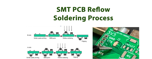
Reflow soldering has become the dominant assembly method in modern electronics manufacturing, offering numerous advantages over traditional hand soldering or wave soldering techniques. This process involves applying solder paste to printed circuit boards (PCBs), placing components, and then heating the entire assembly in a precisely controlled thermal environment to create permanent solder joints.
As electronic components continue to shrink in size while growing in complexity, understanding the critical aspects of reflow soldering becomes increasingly important for ensuring product reliability and manufacturing yield. This article examines the essential considerations for successful reflow soldering operations.
1. Solder Paste Selection and Handling
1.1 Choosing the Right Solder Paste
The foundation of any reflow soldering process begins with selecting appropriate solder paste. Key factors to consider include:
- Alloy composition: Common choices are SAC305 (Sn96.5Ag3.0Cu0.5) for lead-free applications or Sn63Pb37 for traditional soldering
- Particle size: Typically classified by IPC J-STD-005 (Type 3 for most SMT, Type 4 for fine pitch, Type 5 for ultra-fine pitch)
- Flux chemistry: No-clean, water-soluble, or rosin-based formulations each have different characteristics
- Viscosity: Must be appropriate for your stencil printing process and component types
1.2 Proper Storage and Handling
Solder paste requires careful handling to maintain quality:
- Store at recommended temperatures (typically 0-10°C for most pastes)
- Allow proper thawing time (4-24 hours at room temperature before use)
- Implement first-in-first-out (FIFO) inventory management
- Monitor shelf life and do not use expired material
- Keep containers sealed when not in use to prevent drying
2. Stencil Design and Printing Process
2.1 Stencil Design Considerations
The stencil determines how solder paste is deposited on the PCB:
- Aperture design: Should account for area ratio and aspect ratio requirements
- Thickness selection: Typically 0.1-0.15mm for standard components, thinner for fine pitch
- Aperture wall finish: Laser-cut with electropolishing provides best results
- Nanocoating: Can improve paste release for challenging designs
2.2 Printing Process Parameters
Consistent printing is critical for good soldering results:
- Squeegee pressure: Typically 5-15kg force depending on stencil size
- Print speed: 10-50mm/sec, with slower speeds often providing better results
- Separation speed: 0.1-3mm/sec to ensure clean release from stencil
- Print gap: Should be nearly zero for most applications
- Cleaning frequency: Regular underside wiping (every 2-10 prints) maintains quality
3. Component Placement Considerations
3.1 Placement Accuracy
Modern surface mount devices require precise placement:
- Fine pitch components may need placement accuracy of ±0.025mm
- Large components require careful alignment to prevent tombstoning
- Nozzle selection should match component size and weight
3.2 Moisture Sensitivity
Many components are moisture-sensitive:
- Follow MSL (Moisture Sensitivity Level) classifications
- Proper baking may be required before assembly
- Time limits between baking and reflow must be observed
4. Reflow Profile Development
4.1 Understanding the Reflow Profile
A proper thermal profile consists of four main phases:
- Preheat/ramp: Gradual temperature increase (1-3°C/sec)
- Soak/preflow: Allows flux activation and temperature stabilization
- Reflow: Peak temperature above solder liquidus
- Cooling: Controlled descent to solidify joints properly
4.2 Key Profile Parameters
Critical parameters that must be optimized:
- Peak temperature: Typically 20-40°C above solder liquidus (215-245°C for SAC305)
- Time above liquidus (TAL): 30-90 seconds for most applications
- Ramp rates: Controlled to prevent thermal shock or paste splatter
- Cooling rate: Affects joint microstructure (typically 1-4°C/sec)
4.3 Profile Verification
Regular profile verification is essential:
- Use multiple thermocouples to monitor different board areas
- Place probes on both large and small thermal mass components
- Verify profile matches solder paste manufacturer recommendations
- Revalidate when changing materials or board designs
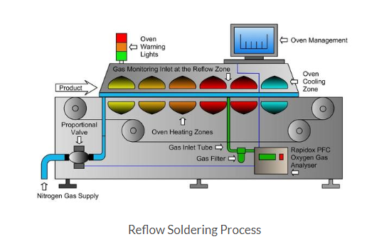
5. Oven Considerations and Atmosphere Control
5.1 Oven Selection Factors
Choosing the right reflow oven involves:
- Heating technology: Convection, IR, or vapor phase
- Zone count and control: More zones allow better profile control
- Maximum temperature capability
- Throughput requirements
- Nitrogen capability if needed
5.2 Nitrogen vs. Air Environment
Nitrogen use affects soldering quality:
- Benefits of nitrogen:
- Reduces oxidation
- Improves wetting
- Allows lower peak temperatures
- Drawbacks:
- Increased operating costs
- Requires oxygen level monitoring
- Typical oxygen levels: <1000ppm for good results
6. Inspection and Quality Control
6.1 Common Defects and Causes
Understanding potential defects helps process optimization:
- Bridging: Often caused by excessive paste or poor stencil design
- Tombstoning: Typically from uneven heating or pad size imbalance
- Voids: Can result from contamination or improper profile
- Cold joints: Insufficient time above liquidus or low peak temperature
- Head-in-pillow: Component warpage or poor wetting
6.2 Inspection Methods
Various inspection techniques are employed:
- Visual inspection: Manual examination under magnification
- Automated Optical Inspection (AOI): Fast, consistent checking of visible defects
- X-ray inspection: Essential for BGA and other hidden joints
- Cross-sectioning: Destructive testing for process validation
7. Process Documentation and Control
7.1 Maintaining Process Control
Consistent results require strict process control:
- Document all process parameters (temperatures, times, equipment settings)
- Implement change control procedures for any modifications
- Maintain calibration records for all critical equipment
- Establish clear work instructions for operators
7.2 Statistical Process Control (SPC)
SPC methods help maintain quality:
- Track key parameters over time (paste volume, placement accuracy)
- Establish control limits for critical characteristics
- Implement corrective actions when trends approach limits
- Use process capability indices (Cp, Cpk) to quantify performance
8. Special Considerations for Challenging Components
8.1 Mixed Technology Assemblies
Combining different component types requires special attention:
- Through-hole components: May need special adhesives or solder forms
- Large thermal mass components: Require profile adjustments
- Fine pitch devices: Need precise paste volume control
8.2 Bottom-Side Components
Second-side reflow presents unique challenges:
- Component weight limitations to prevent falling off during reflow
- Possible need for adhesive to retain parts
- Profile optimization to protect first-side components
9. Environmental and Safety Considerations
9.1 Fume Extraction
Reflow soldering produces potentially harmful fumes:
- Install proper ventilation systems
- Position exhaust points near solder paste application areas
- Consider fume filtration for operator protection
9.2 Waste Management
Proper handling of soldering byproducts:
- Dispose of solder paste containers appropriately
- Recycle solder dross and waste where possible
- Follow local regulations for chemical disposal
10. Continuous Improvement Practices
10.1 Data Collection and Analysis
Implement systems to track:
- Defect rates by type and location
- Process parameter trends
- Equipment performance metrics
- Material usage and waste
10.2 Root Cause Analysis
When issues occur:
- Use structured problem-solving methods (5 Whys, fishbone diagrams)
- Verify corrective action effectiveness
- Document lessons learned for future reference
Conclusion
Successful reflow soldering requires attention to numerous interrelated factors, from initial material selection through final inspection. By understanding and carefully controlling each aspect of the process—solder paste handling, stencil printing, component placement, thermal profiling, and quality verification—manufacturers can achieve high yields and reliable solder joints.
As electronic assemblies continue evolving with new materials, smaller components, and more complex designs, the importance of proper reflow soldering techniques will only increase. Implementing robust process controls, maintaining thorough documentation, and fostering continuous improvement practices will help ensure consistent, high-quality results in any reflow soldering operation.
Remember that each assembly may have unique requirements, and process parameters should always be validated for specific applications. Regular training for operators and technicians, combined with staying current with industry developments, will help maintain an optimized reflow soldering process capable of meeting today’s demanding electronics manufacturing challenges.