Understanding Circuit Relay Diagrams: A Comprehensive Guide
Introduction to Circuit Relay Diagrams
Circuit relay diagrams are essential tools in electrical engineering and electronics, providing a visual representation of how relays function within an electrical system. These diagrams serve as blueprints for designing, troubleshooting, and maintaining relay-based circuits across numerous applications—from industrial control systems to automotive electronics and home automation.
Relays are electrically operated switches that use an electromagnet to mechanically control one or more sets of contacts. This electromechanical action allows a small electrical signal to control a much larger electrical load, making relays fundamental components in power systems, protection circuits, and control applications. Understanding how to read and interpret circuit relay diagrams is therefore crucial for engineers, technicians, and hobbyists working with electrical systems.
Basic Components of a Relay Circuit
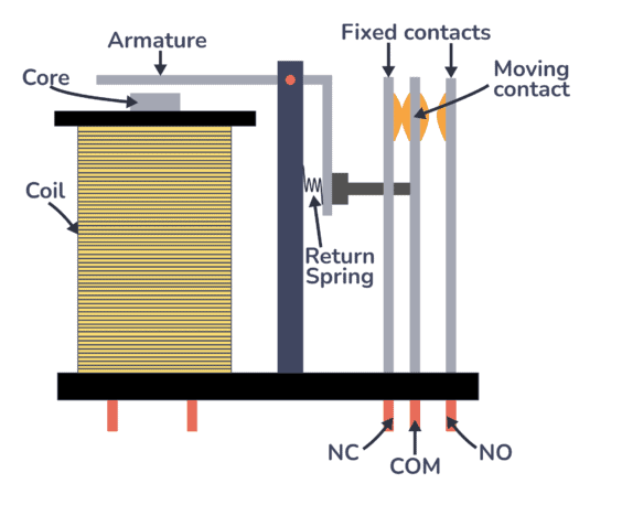
Before examining complete diagrams, it’s important to understand the fundamental components that make up a typical relay circuit:
- Coil: The electromagnet that creates the magnetic field when energized, causing the relay to switch states
- Common terminal (COM): The central contact that moves between positions
- Normally Open contact (NO): The contact that connects to COM when the relay is energized
- Normally Closed contact (NC): The contact that disconnects from COM when the relay is energized
- Armature: The movable mechanical part that physically changes position
- Spring: Returns the armature to its default position when the coil is de-energized
These components work together to create the switching action that makes relays so valuable in electrical systems. The coil, when energized by a control signal, generates a magnetic field that pulls the armature, changing the state of the contacts. This basic principle underlies all relay operations, though modern relays may implement this functionality through solid-state electronics rather than mechanical movement.
Reading Relay Circuit Diagrams
Circuit relay diagrams use standardized symbols to represent the various components and their interconnections. The International Electrotechnical Commission (IEC) and the American National Standards Institute (ANSI) have established symbol standards that are widely adopted, though some variations exist between regions and industries.
Relay Symbols
The most common symbol for an electromechanical relay shows the coil as a rectangle (IEC) or a circle with “CR” designation (ANSI), with the contacts represented by parallel lines indicating their switching state. The normally open (NO) contact is shown as an open gap, while the normally closed (NC) contact shows a connected line. The common terminal is typically represented by an arrow or pivoting line.
Contact Arrangements
Relay diagrams also indicate the contact arrangement, which describes how many poles (separate circuits) the relay can switch and how many throw positions (connection options) each pole has. Common configurations include:
- SPST (Single Pole Single Throw): Simplest form with one circuit that opens or closes
- SPDT (Single Pole Double Throw): One common terminal connects to one of two others
- DPST (Double Pole Single Throw): Two separate circuits that open/close simultaneously
- DPDT (Double Pole Double Throw): Two separate circuits each with two connection options
These configurations are clearly marked on circuit diagrams to indicate the relay’s switching capabilities.
Common Relay Circuit Configurations
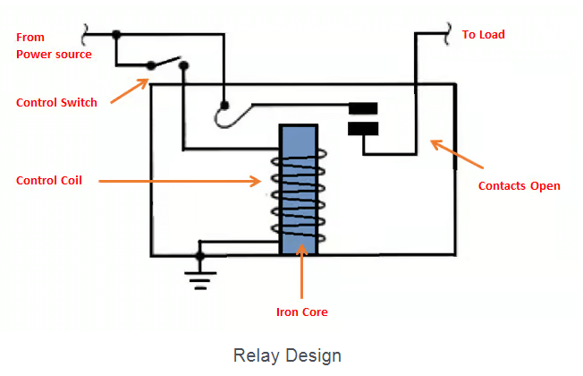
Basic Relay Control Circuit
The most fundamental relay circuit consists of:
- A power source for the coil (typically low voltage DC)
- A switch or control device to energize the coil
- The relay coil itself
- A separate power source and load connected through the relay contacts
This configuration allows a small control signal to switch a much larger load current, providing isolation between control and load circuits.
Latching Relay Circuit
Latching relays maintain their state after being pulsed, requiring no continuous power. Their circuits include:
- Two separate coils (set and reset) or one coil with polarity reversal
- Momentary switches for changing states
- Often includes status indicators
These are common in applications where power conservation is important or where the relay must maintain its state during power failures.
Time Delay Relay Circuit
Time delay relays incorporate timing functions, with circuits that may include:
- RC networks for timing control
- Adjustable resistors for delay setting
- Trigger inputs and output contacts
- Often implemented with solid-state components
These are widely used in motor control, lighting systems, and industrial sequencing applications.
Practical Applications and Diagram Examples
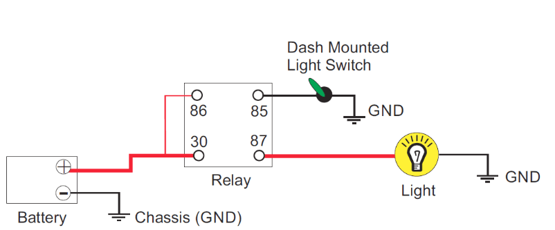
Automotive Relay Wiring
Automotive systems frequently use relays to control high-current devices like headlights, fuel pumps, and cooling fans. A typical automotive relay diagram shows:
- Terminal 85: Coil ground connection
- Terminal 86: Coil power from switch
- Terminal 30: Battery power input
- Terminal 87: Output to load (NO contact)
- Terminal 87a: NC contact (if present)
This standardized numbering helps technicians quickly identify connections during installation and troubleshooting.
Industrial Control Circuits
Industrial relay diagrams often involve multiple relays working in sequence, showing:
- Control voltage sources
- Multiple relay coils with identifying labels (CR1, CR2, etc.)
- Interlocking contacts between relays
- Safety circuits and emergency stops
- Load connections with current ratings
These more complex diagrams require careful study to understand the sequence of operations.
Home Automation Systems
Modern smart home systems use relay diagrams to show:
- Low-voltage control signals from controllers
- Relay modules with multiple channels
- AC load connections
- Often incorporate solid-state relays
- May include network communication lines
Advanced Topics in Relay Circuit Diagrams
Solid State Relays (SSRs)
While traditional electromechanical relays use moving parts, SSRs use semiconductor devices to perform switching. Their diagrams show:
- Input control terminals (often opto-isolated)
- Output power semiconductors (thyristors, TRIACs, or MOSFETs)
- Heat sink requirements
- Often include zero-crossing detection circuits
Protective Relay Circuits
In power systems, protective relays monitor conditions and trigger circuit breakers. Their diagrams include:
- Current and potential transformer inputs
- Sensing and comparison circuits
- Trip coil connections
- Backup protection schemes
- Often use ANSI device numbers for standard functions
Relay Logic Systems
Before programmable controllers, relay logic performed industrial control. These diagrams show:
- Series and parallel contact arrangements
- Latching circuits
- Sequence control
- Interlocking for safety
- Often resemble ladder logic diagrams
Best Practices for Drawing Relay Diagrams
Creating clear, accurate relay diagrams requires adherence to certain principles:
- Use standard symbols: Consistently apply recognized symbols from IEC or ANSI standards
- Label all components: Clearly identify relays, contacts, and connections
- Show complete circuits: Include power sources, loads, and all interconnections
- Maintain logical flow: Arrange the diagram to show signal or power flow clearly
- Include notes: Add specifications like voltage, current, and timing values
- Use cross-referencing: For complex systems, reference related diagrams or contact designations
- Color coding: When helpful, use colors to distinguish different voltage levels or signal types
Troubleshooting Using Relay Diagrams
Effective troubleshooting relies heavily on properly interpreting relay diagrams. Key steps include:
- Verify coil energization: Check control voltage reaches the relay coil
- Check contact continuity: Confirm contacts make/break as designed
- Inspect mechanical linkages: For electromechanical relays, look for physical issues
- Measure load parameters: Ensure the switched load operates within specifications
- Sequence verification: In complex systems, confirm proper operation sequence
- Compare actual to diagram: Look for discrepancies between wiring and documentation
The Evolution of Relay Diagrams
As technology advances, relay diagrams have evolved from purely electromechanical representations to include:
- Solid-state components: Showing semiconductor-based switching
- Programmable logic: Incorporating PLC-controlled relay functions
- Networked systems: Depicting relays controlled over communication buses
- Smart relays: Including internal logic and programming interfaces
- Virtual relays: In software-defined power systems
Despite these changes, the fundamental purpose remains: to clearly communicate how relay-based circuits operate.
Conclusion
Circuit relay diagrams form an essential language for electrical and electronic systems, enabling professionals to design, implement, and maintain relay-controlled circuits across countless applications. From simple SPST switches to complex industrial control systems, understanding these diagrams provides insight into how small control signals manage significant electrical loads.
As relay technology continues to evolve—incorporating solid-state components, networking capabilities, and intelligent features—the diagrams representing them will likewise develop. However, the core principles of clear symbol usage, logical layout, and accurate representation will remain constant.
Mastering circuit relay diagrams requires practice and experience, but the investment pays dividends in the ability to work effectively with electrical systems of all types. Whether for automotive applications, industrial controls, home automation, or power system protection, these diagrams serve as indispensable tools for anyone working with electrical circuits.